

Speaker to Room Calibration Walkthrough
Entry posted by mitchco
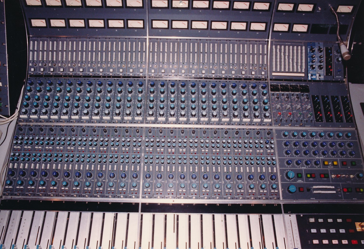
While visiting a friend in The Big Smoke recently, I had an opportunity to assist in tuning a set of DIY speakers to his critical listening environment. This is a walkthrough of what we did, how it sounded, and lessons learned. I tried to present this in a step by step format so if desired, by following the same steps, you could obtain similar results. Here is pic of my friend’s rig:

Let’s inventory the gear. The DIY satellite speakers are enclosed in a designed (using Thiel Small parameters) sealed box using a Seas 6 1/2” woofer that has a characteristically smooth frequency response. The tweeter is an interesting Philips ribbon design.

The passive sub-woofer is a sensitivity matched 10” Pioneer polypropylene driver with a dual voice coil that replaced the original Paradigm driver in which the surround rotted away.

In the above picture, the bass cabinet is upside down showing the two vented ports on the bottom. The speaker is mounted such that if the ports are facing the rear wall, the speaker is facing the listening position (i.e. firing forward).
In my friends listening tests, plus mine, we found the bass response was smoother with the driver firing towards the rear wall, with the ports facing the listening position. The bass frequency response was smoother, both from a listening, and as it turns out, a measurement perspective.
The satellites and passive sub are powered by 100 watt per channel vintage NAD power amplifier, using the preamp section of the NAD integrated amplifier to drive the amp.

Source music is iTunes on an iMac G5.
Here is a check list I assembled for this calibration task. As mentioned at the top of the article, I tried to write it in easy to perform steps.
Step 1 Check to see if the speakers and listening position can be set up in an equilateral triangle.
It is not the end of the world if it can’t be done for whatever reason. In my friend’s case, given the limited space, this is how it turned out. But once the speakers were tuned to the room, it was impressive to hear the rock solid 3D soundstage that these speakers reproduce. There are a couple of reasons for this that will be brought forward later.
Here is an example "blueprint" of the type of speaker to room interface setup required for playback if the goal is to hear what the mixing engineer intended to be heard as accurately as possible. This means trying to achieve symmetry as close to a tight tolerance as possible. Measuring the symmetry (i.e. physical distance) between speakers, walls, and listening position is the key to accurately reproducing (i.e. decoding) the soundstage.

Here is the specification.

Both Dolby Labs, “5.1 Channel Music Production Guidelines”, http://www.dolby.com/uploadedFiles/zz-_Shared_Assets/English_PDFs/Professional/4_Multichannel_Music_Mixing.pdf and “ITU-R BS.775-1* MULTICHANNEL STEREOPHONIC SOUND SYSTEM”, http://www.gearslutz.com/board/attachments/bass-traps-acoustic-panels-foam-etc/234800d1305311642-sticky-links-itu-r-bs775-1.pdf (and ANNEX 1 for stereo) have similar “specifications” when it comes to interfacing the speakers to the room.
Full disclosure, in a previous career, I worked as a recording/mixing engineer for 8 years. I was fortunate enough to have worked in very nice control rooms, with state of the art acoustics and monitoring. I was lucky to have been involved in the ground up build of this facility with Chips Davis: http://chips-davis.com/ I learned a lot. By far the best sounding critical listening environment I have ever heard.

Those Urei/JBL 813B "time aligns" were being driven by 2.4 kilowatts of Crown power. The bottom end was super tight and still went to 20 Hz. Using the mid and high frequency trim pots, we would adjust the tonal balance to typically that of the B&K target frequency response (discussed later). This was the only eq required as the room itself was designed and built to be as acoustically transparent as physically possible (LEDE certified). Almost all pro facilities since then are based off of this deign. It was a revolution in control room design.
In order to certify a mixing, mastering, broadcast, video post-production, critical listening, etc., facility, it means implementing this specification. So if the goal is to accurately reproduce what the mixing engineer hears in their chair, it makes sense to use the same specification in our own critical listening environments.
Note this is how stereo and 5.1 music is mixed using this "speaker to room" specification. If we want to properly “decode” what was mixed, then our speakers to room interface should conform to this specification. The Dolby document, “5.1 Channel Music Production Guidelines” is a great read. Even though a bit dated gear wise, almost every piece of music we listen to has been recorded, mixed, and mastered using this speaker to room interface specification.
Step 2 “Voice” the speaker to room interface by using the following two methods. One is by ear the other using REW acoustic measurement software. Let’s go by ear first.
By Ear. I voice (i.e. play music on) one speaker at a time. I play music that has a solid bass line, preferably with a wide range of notes. Ideally a bass line that produces significant output at 20 Hertz and moves up and down the musical scale.
What we want to do is listen to the music while moving the speaker either closer or further away from the rear wall. Here is the method I use. Looking at my friend’s setup, I would stand parallel, facing the side of one of the speaker cabinets. One ear is focused towards the listening position, with the other ear focused on the wall behind the speakers. So I am standing 90 degrees perpendicular (i.e. sideways) to how I would normally sit and listen to the stereo.
While the music is playing, on one speaker at a time, I am slowly moving the speaker either forward out into the room or backward towards the wall. What am I listening for? I am listening for the evenness of the bass notes. As the bass notes are playing up and down the musical scale, each note should sound equal in level (i.e. loudness) to the ear. Technically, I am trying to “hear” the room modes.
If one or more different bass notes drops quite a bit in level that means I am in a position in the room where those bass notes (i.e. range of frequencies) cancel each other out or in a “null” spot. Conversely, if some bass notes sound loud or boomy, relative to other notes, then I am standing in a position in the room where those bass notes add together. However, there is likely one or more spots in the room where the speaker’s bass notes sound the most even. That’s where the speakers should be placed, if the geometry works out. In other words start with a rough equilateral triangle and fine tune from there.
Here is an illustration that animates this concept of waves adding or canceling depending on room position.

Further reading: http://www.acs.psu.edu/drussell/Demos/superposition/superposition.html
Note this is relative to the listening position as well, which further complicates the mixing of waveforms. Ideally, the listening position is as far away from all reflecting surfaces as possible. This means towards the middle of the room. Called, a reflection free zone. Here is a picture of my critical listening environment, when I remove the table that is. The listening position is away from the rear and side walls as much as possible. The floor and ceiling and wall/glass behind the speakers are the early reflectors, but are dampened by the thick carpet I have between the speakers and listening position.

Back to my friends room. Another way to voice the speakers to room interface is by using a computer software measurement system. Fortunately, high resolution software measurement systems, too expensive ten years ago, are now state of the art for a commodity price or even free.
One such fine piece of measurement software is REW http://www.hometheatershack.com/roomeq/ , which unbelievably is free. In conjunction with a calibrated measurement microphone http://www.content.ibf-acoustic.com/catalog/product_info.php?cPath=30&products_id=35 this state of the art measurement system can assist in optimizing any speaker to room interface. In fact, given the computing power, sophisticated measurement software, and calibrated mic, the resolution of the measurements made by this system exceed what our ears are capable of hearing.
First we need to calibrate the sound card. What this means is that the REW software is going to measure the frequency response of the sound card and if there are any deviations from “flat” from 20 Hz to 20 KHz, the “calibration file” will compensate. This takes any of the sound card’s frequency response variations out of the measurement equation. That way we are measuring the true frequency response of the device under test, which in our case are the speakers in the room.
This is the measurement of my Lynx L22 pro sound card, frequency response is flat out past 50 KHz. Since this measurement is taken in external loopback mode, the frequency response is the combined response of both the input/output analog amplifiers and ADC/DAC components. You achieve external loopback by connecting the output of your sound card back to the input of same sound card. You can find good instructions here: http://www.hometheatershack.com/roomeq/wizardhelpv5/help_en-GB/html/calsoundcard.html#top

As an aside, it is amazing to me that the onboard chip in my Dell laptop has an ADC and DAC that supports up to 24/192. This is the onboard chip! Soon we will see this level of DAC in smart phones.
The same calibration approach applies for the measurement microphone as well. We want to plug in its calibration file, supplied by the microphone manufacturer, into the REW software. One of the reasons I like this measurement kit http://www.content.ibf-acoustic.com/catalog/product_info.php?cPath=30&products_id=35 is because the mic preamp is calibrated to the microphones sensitivity. This means I can calibrate SPL’s as well if I want to meet a proposed monitoring level specification like Bob Katz’s K System: “An Integrated Approach to Metering, Monitoring, and Leveling Practices” http://www.digido.com/level-practices-part-2-includes-the-k-system.html Excellent read and proposal in my opinion.
My mic comes with two calibration files, one for the mics on axis frequency response for when the mic is pointing down the center line towards the speakers, and 90 degree off axis response for when the mic is pointing up. I have used both and for room measurements, I prefer the 90 degree diffuse field correction. Also relevant if you are tuning a 5.1 system.
Here is my mic’s calibration file. This is the frequency response graph and partially what the 2 calibration files contain from 20 Hz to 20 KHz.


This is a pic of the microphone position used for the following measurements in my friend’s listening room. Note that the listening position is at the back wall, as opposed to the middle of the room, as space is limited. There is a sneak peek of the frequency response graph on REW’s software.

Now we are in a position to measure the frequency response, but first we need to set some levels and calibrate the SPL. That is covered in REW’s guide: http://www.hometheatershack.com/roomeq/wizardhelpv5/help_en-GB/html/measurementlevel.html#top and http://www.hometheatershack.com/roomeq/wizardhelpv5/help_en-GB/html/inputcal.html#top
But before we take any full range frequency measurements, we want to “voice” the speaker’s low frequency response to the room, like we did with our ears. In some respects, this is a validation that we have found the right spot based on our ear’s voicing of the room.
Aside from swept sine waves, we can use REW’s Real Time Analysis (RTA) function to pressurize the room (like blowing on a coke bottle to form the resonances). We output pink noise for low frequencies, and while watching the real–time display, moved the speaker/sub combo to and from the rear wall to achieve the most even response possible. As it turns out, where I voiced the speakers by ear turns out to be the same spot that measures the flattest frequency response in the low end. Here is what that looks like in REW:

Step 3 Now measure up and ensure we have the best possible symmetry to within a 1/4” tolerance.
Based on voicing the speaker to room interface for low frequency response, we need to ensure that each speaker is exactly the same distance from the rear wall. While I have used tape measures in the past, it is truly worth the investment in a digital laser measurer like http://www.amazon.com/Bosch-DLR130K-Digital-Distance-Measurer/dp/B001U89QBU
Why? Here is a bit of math to better understand why this is important: http://www.sengpielaudio.com/calculator-wavelength.htm This is a wavelength calculator. If I type in 20,000 Hz, the wavelength is 0.675 of an inch. That’s a little more than a 1/2". So if my equilateral triangle is out, or off center, or the distance from the speakers to the rear wall are different, then “comb filtering” occurs. All it takes is for the tolerance to be out slightly more than a 1/2". It not only affects the frequency response, but the soundstage as well. Ethan Winer does an awesome job explaining this: http://ethanwiner.com/believe.html
Bottom line. Try and ensure that the equilateral triangle between the speakers and listening position is within a 1/4” tolerance. Same goes for the distance between the speakers and the rear and side walls. Try and make it as symmetrical as possible. I shoot for a 1/16” – 1/8” to a 1/4" max. tolerance. I learned this from Chips Davis. When that studio was built in 1986, he used a laser survey standard to layout out the room from the blueprints. He viewed it as the most critical part of the build and spent a great deal of time getting it right on the button for every measure.
It may take a couple hours of work, measuring distances, readjusting, re-measuring, rinse and repeat, down to below 1/4" tolerance. The reward? Most people have not heard this level of precision towards neutral tonal balance and decoding of the soundstage.
Here is a pic using the laser distance measurer to ensure both speakers are exactly the same distance (I got it down to a 1/16” tolerance) from the rear wall.

Step 4 measure the frequency response of each speaker (and sub). Now that everything is configured to a tight tolerance, sound card and mic calibrations loaded into REW, we can take a full range measurement.

A couple of points to keep in mind while looking at this frequency response plot. One is that the REW software has considerably more measurement resolution than our ears do. “The ear tends to combine the sound within critical bandwidths, which are about 1/6 octave wide (historically thought to be 1/3 octave). This has led to the practice of averaging frequency response over 1/3 octave bands to produce beautiful-looking frequency response curves. In my opinion this is misleading.” From “Music and The Human Ear” Another excellent read in my opinion: http://www.silcom.com/~aludwig/EARS.htm
I agree. I use 1/6 octave smoothing on the measured frequency response, which more closely represents how our ears hear. Here is the same frequency response as above, except with 1/6 octave smoothing applied.

Major difference and provides a clue as to how much (displayed)resolution the software and components are capable of measuring.
I know it seems far away from a flat frequency response, as compare to the frequency response of the Lynx L22 sound card above. To quote Ethan Winer, "The room you listen in has far more influence on what you hear than any device in the signal path, including even the loudspeakers in most cases." I agree.
For example, here is the frequency response of one of my speakers in my listening room:

Similar, but different than my friends room. However, unfortunately, typical of small room acoustics. All of our listening environments suffer from this. Some more than others. To look into this more, I highly recommend Bob Gold’s Room Mode Calculator: http://bobgolds.com/Mode/RoomModes.htm to plot the room modes, cut off frequency, and other important acoustical parameters to take into consideration.
To better understand the output of the calculator, Ethan Winer, again, does an excellent job of explaining this and what can be done in his article, “Acoustic Treatment and Design for Recording Studios and Listening Rooms: http://www.ethanwiner.com/acoustics.html
As an aside, when we were running REW full range sine wave sweeps, there was an audible “chirp” detected in the right speaker. It was for just the briefest moment of time, but still audible during the sweep. We ran the test a number of times while feeling around the cone of the Seas driver. As it turns out, while we were soldering a connection earlier, we forgot to tighten up one of the bolts that mounts the driver. So we were hearing the vibration of the speaker frame against wood at a certain resonant frequency due to one bolt not being tightened up. After tightening the bolt, and re running the sweeps, the chirp was gone.
Btw, other folks are obtaining similar results. CA’s own Nyal Mellor and Dallas Justice worked together to use acoustic measurements for speaker placement: http://www.whatsbestforum.com/showthread.php?6050-A-good-example-of-how-to-use-acoustic-measurements-to-place-speakers
Great job!
CA’s wgb113 also wrote a blog post: http://www.computeraudiophile.com/blogs/Room-EQ-Wizard Nice frequency response!
Another interesting speaker room calibration discussion is Bruce Brown, The Pro Audiophile: http://www.whatsbestforum.com/showthread.php?5893-Speaker-Room-calibration
Step 5 Calibrate the speakers to a known target frequency response reference.
So now that I have measured the frequency response, now what? Considerable research and listening tests show that we do not want or prefer a “flat” 20 Hz to 20 KHz frequency response at the listening position. In fact, most of the research shows that we prefer a “target” frequency response at the listening position to be sloped downward from 20 Hz to 20 KHz, typically down -6dB at 20 Khz.
Reading this excellent paper from B&K, http://www.bksv.com/doc/17-197.pdf and based on the listening/measurement tests, the “optimum” target frequency response at the listening position is:

Translating the target frequency response into numbers: 0 dB at 20Hz, -0.5 dB at 200 Hz, -3.0 dB at 2 KHz, and -6 dB at 20 KHz. In addition, looking at the work Dr. Sean Olive http://seanolive.blogspot.ca/2009/11/subjective-and-objective-evaluation-of.html has done, both in measuring and listening tests, a very similar frequency response "slope" emerges as the preferred frequency response curve at the top of this diagram: https://docs.google.com/file/d/0B97zTRsdcJTfY2U4ODhiZmUtNDEyNC00ZDcyLWEzZTAtMGJiODQ1ZTUxMGQ4/edit?hl=en_US&pli=1

It is also stated that listeners do not prefer a “flat” frequency response, but rather the downward sloped response. “Flat in-room response is not the preferred target” from Sean’s slides.
I concur, here is the frequency response of one of my speakers at the listening position, corrected for perfectly flat. I am using Digital Room Correction (DRC) to achieve this flat response of 20 Hz to 20 Khz +- 3db at the listening position. It is definitely too bright and has another consequence of moving the soundstage too far forward. Note these graphs are 1/12 octave smoothing.

Because I use DRC software (i.e in the digital domain), I can easily change the “target” frequency response in less than a few minutes and be listening to a different “calibration”.
Here I am following the “optimum” B&K and similar Harman target frequency response at the listening position.

To my ears, and obviously to the folks that took the tests in both articles, this frequency response “slope” at the listening position sounds the most natural. It’s not too bright, not too dull, but just right. It also has the best sound stage in my opinion, not too far back, not too far forward, but just right. To my ears, best resembles the tonal balance that I took for granted while working in those state of the art acoustic and monitoring facilities.
Because of the ease in which I can change target frequency response, I have listened to dozens of different target frequency responses. By doing this, I have learned that a few dB up or down deviation from the B&K and Harman target's, makes a big difference in tone quality (i.e. timbre) and sound stage. That is why it is critical to calibrate the sound card and have a calibrated microphone, as a few dB off calibration makes a big difference and can produce incorrect results.
So how does this help my friends room tuning? Well, he has tweeter level controls so I can “calibrate” the frequency response slope to match my target frequency response that I know is already calibrated to a known target. Here I have overlaid 3 frequency responses. The one in blue is my friends, the one in green is mine, and the one in red is mine also, but with DRC (Audiolense) enabled.

It is not a fair comparison as I am using DRC (which makes a significant difference). But the point being is that I can match the high frequency response “slope” of my friends speakers to match the target for the best tonal balance and soundstage. Our listening tests confirmed that this is the right tonal shape at the listening position, even if the bottom end is a bit more variant in frequency response.
Step 6. Repeat as required. It may take a few iterations to fine tune the system as there are a lot of variables involved. For example, while the mic was pointing straight up, I used the wrong calibration file which accounts for a 4 dB difference at 20 KHz. Noticeable. You may want to space apart the iterations over days so that you can settle in and form an opinion as to the sound quality.
It has been my experience that there is a direct correlation to what we measure and see with graphs with what we hear. It just takes practice and patience to tune into both and correlate the two. If you take some DRC software for a spin, make sure you can quickly switch between targets. It is very interesting to see that small measured changes in frequency response slope, makes for large audible tonal and soundstage changes.
Conclusion
“The room you listen in has far more influence on what you hear than any device in the signal path, including even the loudspeakers in most cases”. As quoted from Ethan Winer. I would say by orders of magnitude difference based on my experience. This is where significant improvement to any existing sound system can be had for a relatively small investment.
Where to go from here?
If you are interested in Digital Room Correction (DRC), and advanced topics like True Time Domain correction (i.e. time alignment), I wrote a series of articles called, “Hear music the way it was intended to be reproduced” starting with: http://www.computeraudiophile.com/entries/6-Hear-music-the-way-it-was-intended-to-be-reproduced-part-1
Note with Audiolense DRC, your head is not “locked” into one mic position. Audiolense has the capability for multi-seat DRC so that you can tune the sweet spot to cover a couch area, for example:

If DRC is not for you, then try some simple passive acoustic treatments. This is a great starting point: http://www.gearslutz.com/board/studio-building-acoustics/610173-acoustics-treatment-reference-guide-look-here.html
Digital Audio has been around since the early 80’s, that’s 30 years ago. According to Moore’s law, http://en.wikipedia.org/wiki/Moore%27s_law we are using computing power that contains 100,000 times more transistors than in 1980. Today we have very advanced software working at 64 bit data paths, http://wiki.jriver.com/index.php/Audiophile_Info where noise and distortions are below our ability to hear them. That means Digital Room Correction, using digital FIR filters, has no audible effect on the sound quality when inserted into the playback chain.
REW is powerful acoustic measurement software as it can also measure Energy Time Curves (ETC’s) which will help you achieve a reflection free zone in your listening area. Also using REW’s waterfall measurement capability will show how sound decays in your room, typically over a 300 millisecond window. This is useful to see if bass traps are required as this is the most common problem, along with early reflections...
My goal in writing this was to walkthrough a typical speaker to room calibration and demonstrate the benefits of such an effort in hopefully easy to perform steps.
After a month of listening, my friend is very happy with the end result (both audible and visual).
Happy Listening!


27 Comments
Recommended Comments