One and a half Posted June 29, 2015 Share Posted June 29, 2015 I made my own AC cable for the amp using separate shielded single core: it's better than the stock cable. Interesting thought about the iso transformer before the balanced power. As for stopping each device affecting the other, this is precisely what my AC filter is planned for: since each component has its own filter line, it is very difficult for one component to affect another one. Using the Isolation transformer in front of the Balanced power transformer does two things. 1. To slow the current peaks from the balanced transformer primary, so it acts like a choke. 2. Provide some soft starting for the balanced transformer. There is no overlap, the isolation transformer and balanced transformer do different jobs. If you had to choose and just use the one device, the balanced transformer would be it. Depending on how much rubbish there is on the secondary of the balanced transformer, this out of balance rubbish has to go somewhere, and ends up in the primary windings as an acoustic noise. Use of an isolation transformer connected upstream of an Equitech transformer is a recommended practice from Equitech. I found the use of a standard line conditioner in front of the Equitech restricted the dynamics and made the bass almost non existent. Would not recommend to use this device. Downstream is also a problem, since it regards the Equitech balanced supply as a fault although the filtering does work better on a balanced supply (if it uses a typical T filter). To avoid cross contamination between components is not that simple, since an audio component will provide a different spectrum. The injection mains side spectrum from an amplifier is different to a CD player or computer, so the filter should be tuned individually. You can add standard EMC filters PLUS use the balanced supply, since the filters work better on a symmetrical supply, rather than one side grounded if you still wanted to keep the filters. The balanced transformer does a great job of providing an effective cross pollution from other components on its own. Having several filters in parallel could cause a surprise in that there could be a resonance condition, but not likely. AS Profile Equipment List Say NO to MQA Link to comment
One and a half Posted June 30, 2015 Share Posted June 30, 2015 There is neither an inductor nor a switch on the ground line in my current build. I don't plan to integrate the latter either - I think Lukasz thought it a good way at the time to easily prevent ground loops if hums occur, but if I had to put a switch it would never be on that line... As for the caps from L, N to G (or H, N to SG/PE so long as we understand each other), I think the dumping of noise is precisely the goal, but solely for high frequency noise. So I believe the diversion to ground is deliberate, but that's also why I was asking earlier about how to properly implement the inter-component contamination isolation as currently, there doesn't seem to be anything to prevent the noise along the GND line from one component from going to the next one. How would you do it? Managed to do some additional building and testing tonight - see below - including a very controversial finding (for many). Thanks for the reference info, speedskater. I have Ott, Brown/Muncy lined up for further reading/research and already watched two of Armstrong's videos on Youtube, the earlier ones have bad sound, but the content is useful. Agreed, the use of any impedance or device in a protective earth is prohibited, you just can't do this. Just looking at the circuit, the two caps, if you tie them to the neutral, can cause GFCI devices to trip at switch on. That filter BTW will work well on a balanced circuit than from a TN system. AS Profile Equipment List Say NO to MQA Link to comment
One and a half Posted June 30, 2015 Share Posted June 30, 2015 @ One and a Half ... Thank you for your post. I have seen you previously recommend; Isolation Transformer upstream of Balanced Power transformer. Previously I was doing it the other way around (due to wattage capacity of my power supplies), though I have long been curious about doing it the way you suggest (seen you mention it in other posts). Well, I ordered a larger Isolation Transformer so I could do as you suggest. Tonight it arrived and it is now upstream of one of my Balanced Power transformers. It is so much better this way. Too busy enjoying to music to write coherent thoughts, though it is a noticeable difference. So thank you ! I appreciate your post above, it helps me understand the why , other people posting on this thread are more knowledgeable than me, so it is great when people like you and others take the time to explain the "why". Anyway, better get back to listening to Melody Gardot's Curreny of Man. You're very welcome, although I wish I could enjoy Melody's new music a little more, just have this barrier with that music and Melody's voice in the same continuum. I tried to feed the Balanced transformer with a 2kVA online UPS, Eaton 9135. I don't know why, but the bass wasn't as pronounced or controlled with the UPS and am mystified why a lot of AC line conditioning equipment and a REGEN can affect these low frequencies. Maybe it's the most dominant energy and noise riding on it? Anyway am back on the Isolation transformer feeding the balanced transformer, and all is good. AS Profile Equipment List Say NO to MQA Link to comment
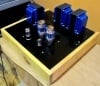
One and a half Posted June 30, 2015 Share Posted June 30, 2015 What do you think of the Tripoint Troy devices? [ATTACH=CONFIG]19476[/ATTACH] Beautiful finish on the timber aren't they. Other than that the tripoint offers similar to the Entrec offerings. Ermm, don't see how a parallel grounding system works when there's a mains earth wire doing the same job. Unless some components don't have an earth connected and the bonding cables are lower impedance than the interconnects to avoid ground loop....the frames are then bonded to earth, by design they aren't. I would really need to listen and the effectiveness totally depends on the rest of the system and AC treatment. Not totally convinced. The line conditioners have filtering which is fine but the techniques are short on details and more on spin. For a true evaluation, an objective test with measurement would substantiate their product. AS Profile Equipment List Say NO to MQA Link to comment
One and a half Posted July 6, 2015 Share Posted July 6, 2015 One recommendation is to have a separate/dedicated ground with a separate ground rod for all audio equipment. Neutral is bonded at the main board to ground. Should neutral for the audio circuit leg be bonded to the house ground or to the dedicated ground? The later option would eliminated any voltage differences between the different grounds and neural and ground within the dedicated audio circuit. Please don't think about an additional separate ground rod. This causes two separate paths to earth, bypassing the protective fuse or circuit breaker. This will charcoal your house. You can though have multiple earth stakes to fill your backyard if you wish, but all of them need to come back to the one point at the switchboard. Voltage differences between earth and neutral can and are caused by harmonics as well as poor contacts. AS Profile Equipment List Say NO to MQA Link to comment
One and a half Posted July 7, 2015 Share Posted July 7, 2015 Why should a separate ground bypass the fuse or circuit breakers (not considering GFI)? A circuit breaker is a switch on the hot leg which switches off the hot leg when there is a over current. It does not care where to currant goes (in contrast to GFI) or is there something I have not considered? There was a good drawing that showed the paths on a fault in a location that had a separate ground rod and why the breaker doesn't trip. Gimme a while to find it. AS Profile Equipment List Say NO to MQA Link to comment
One and a half Posted July 8, 2015 Share Posted July 8, 2015 I suspect that there may be. Where would you be for example, if the secondary of the transformer broke down to it's core ? Perhaps a question for 1 1/2 ? Even when I don't connect any of a circuit to mains earth, I normally mount the transformer (depending on type ) on a metal plate or a piece of copper clad PCB, where only the plate/copper side of the PCB is connected to I.E.C. mains earth. The plate is also spaced a little above the bottom of the case to permit improved ventilation without any protruding bolt heads. If the transformer broke down to the frame, or an live AC wire fell off a terminal and ended up on the metal chassis of an amp say are two scenarios where your interconnects are at mains voltage. Since there's no return to earth no fuse or circuit breaker will blow, the shield on the interconnects will be live, not 1/2 but at full mains voltage. On the contrary, I find that earthing every component, amps, CD, radio and DACs, the lot benefit from being earthed, since the chance of potential differences due to interconnect shield voltages are very, very low and avoids ground loops from day one. I find it irresponsible, perhaps too strong a word, but certainly misguided for Superdad to peel back earth wires and tape them up on equipment that's meant to be earthed. There are ways around ground loops, often difficult to solve sometimes, but bypassing safety systems is not one of them. AS Profile Equipment List Say NO to MQA Link to comment
One and a half Posted July 9, 2015 Share Posted July 9, 2015 Thanks for the clear explanation. To summarize, floating the secondary neutral on the isolation transformer disables the ability of a circuit breaker to detect a short, or over current condition as the common reference is gone. And by implication, any device plugged into the "modified" isolation transformer has it's safety mechanism disabled as well as the reference potential has been changed. Did I get that right? Mmm sort of. Unlike a true reference say a 0V in an audio system, the earth connections in a power grid, are there only for safety in case of faults. The earth conductor is not meant to be used as a working reference point like a 0V. 0V from one audio component to another like an RCA DAC analog out to an amplifier input should be immeasurably the same, but in practice there is enough shield voltage to create a difference. I suppose when the RCA was first utilised the noise floor levels were a lot higher than what can be achieved today, so a little bit of shield voltage (and current) wasn't a problem. High gains and lower noise floors are creeping in to audibility status (for some designs) so the shield voltage is a problem. The trick is to maintain the same earth potential from one component to the other. XLR is one way around this, the other is to use equipotential bonding (pls Google this term). This type of bonding uses large conductors like size 0 something to ensure that the earth bond between various cabinets (in an industrial process for example) is at the same potential. This is mainly used for safety, but has the added bonus of shunting noise to one place (there are exceptions). All shields of cables are tied to the same point, needless to say, the shield is only there for screening purposes, it's not used as a conductor, like our dumbass RCA audio system. If you can, try and use XLR cables and connectors. The earth wires in the audio components power leads and connections inside the components would provide the equipotential bonding between the devices. AS Profile Equipment List Say NO to MQA Link to comment
One and a half Posted July 9, 2015 Share Posted July 9, 2015 . Now some people say that GFCIs are horrible for sound, but THAT is a different issue. John S. Oh dear, another issue for audiophiles. I dunno, a GFCI is really just a current transformer with wires passing through. I guess the wires passing through would not be considered audiophile grade, let alone the contacts and materials used, although small copper bars are used to some extent, and not long crystal and high purity either. I'm not game to remove them in my system to find out though. AS Profile Equipment List Say NO to MQA Link to comment
One and a half Posted July 9, 2015 Share Posted July 9, 2015 Very interesting, jabbr. I had this at the back of my mind because for the time being, I am mostly experimenting with and designing the AC filter, vibration isolation and damping and power & interconnects: 1. Use a couple of similar step-down transformers, wire them secondary to secondary, filter with suitable capacitors in between for an isolation transformer prototype. 2. Derive a balanced power transformer from the iso transformer prototype. I think the iso transformer can replace on integrate one filter line in my box, and possibly the balanced power one will come before the whole filter box (i.e. between mains AC and my filter box). How does that sound? I tried off the shelf toroid 1kVA transformers in balanced design. The success was limited, not overwhelming though. The real eye opener is to use either the Equi-tech, (Furman, BPT or the Torus) transformers. The regulation is a lot tighter overall, and this creates a finer reference balanced voltage. The tighter regulation you have, the more noise is cancelled and the backgrounds are nicely quiet. AS Profile Equipment List Say NO to MQA Link to comment
One and a half Posted July 9, 2015 Share Posted July 9, 2015 Equi=Tech, Furman, BPT and Torus all have used Plitron transformers in their products. The Equi=Tech Q uses a Plitron LoNo. Torus is actually Plitron itself. I am half way through their webinar. It could be interesting to see what can be sourced from them directly. They're in Toronto. For the record Equi=tech have a number of different suppliers of transformer, so it comes down to the best price/performance/availability ratio, the usual commercial decision. The transformer inside my Equi=tech is not a Plitron. AS Profile Equipment List Say NO to MQA Link to comment
One and a half Posted July 9, 2015 Share Posted July 9, 2015 Found some relevant feedback on GFCI in AC conditioners in a post on htguide. Well, there you have it, inadequate size of PCB tracks and contact material is the problem, what a fool Glen B is. YashN, this kind of post serves no purpose other than to show your skills at searching the Internet and increasing your post count. Good luck with Power factor Correction and building it in your AC Filter. See ya later. On the Ignore list you go. AS Profile Equipment List Say NO to MQA Link to comment
One and a half Posted July 13, 2015 Share Posted July 13, 2015 I am just gathering info for learning, One and a Half, and obviously, I cannot know what's a good thing and what's not a good thing until I learn from others who have more experience than me or from my own experimentation when I can. I am not sure what got you so worked up. I don't care about my post count: took me years to get to 1,000. The reason I am worked up about is post #208. If you are still learning, then don't post everything you can find on power related audio topics until you draw a conclusion whether the article is relevant or not by studying more articles with some facts behind them. Deciding relevance requires some knowledge of electrical technology and in many countries working direct/installing equipment with voltages 100V above requires licensing. Hobbyists are not exempt. The article from Ross B pulls apart a GFCI and concludes, gee no wonder they don't sound good, they are made of thin PCB tracks and undersized contacts. He's not the sharpest tool in the shed and don't use his advice or methods. The GFCI is certified, understand certified, to work to save lives by detecting the passive current differences between Hot and neutral conductors, typically 30mA, 10mA or less for hospitals. Passive. Not active. Apart from the contacts and the PCB tracks (which are in just about every modern power amp to keep the track inductance low) there's nothing else in the path, no filtering or other sound degrading qualities. All Russ B does is reduce the wiring path by 2milli Ohms, and perhaps reduces the amount of induction in the GFCI, big deal. Then Russ fits white receptacles on a balanced supply, I'm not in the US, but the outlets need to be orange, labelled and the GFCI put back. AS Profile Equipment List Say NO to MQA Link to comment
One and a half Posted July 29, 2015 Share Posted July 29, 2015 To Mike, To try and keep the shield voltages the same between the amp and DAC, another approach is to bond the chassis of the amp and DAC together with a thicker wire between the two. If you have a spare output RCA jack like the Coax for example on the DAC, crudely get an old RCA connector and crimp a 10AWG single cable on the shell only, and keep the wire short as you can, connect this to any spare input on the amp, once again, don't connect the centre pin, just the outside shell. This should make the shields in the signal leads from the DAC as close as the same, so the only shield voltage is in the length of the audio out of the DAC to the AMP connection. There are a few designs out now from Entrec and a few others offering a grounding network connecting all ends together. Problem is, their cabling is quite long can cause more drama than good. AS Profile Equipment List Say NO to MQA Link to comment
One and a half Posted July 30, 2015 Share Posted July 30, 2015 To Mike, The differences in voltages 117.5 and 109V are due the regulation of the transformers, the original 1st one close to the AC Mains and the combo of the 2nd. If these are loaded, say less than 20%, the voltage will rise. I'd like to know where you measured the voltage. Is it inside the equipment or the lead at the end? Also of interest is the voltage between the Neutral and Ground at the wall outlet. This in theory should be 0.000V AC but typically for house 1-2V, some industrial places are 10V+. These elevated voltages are the result of harmonics, if you have a meter with FFT, you can see the frequencies causing the volts to rise. They could have their origin next door or from your home and are caused by anything other than a bulb. Yes Bill is an outspoken critic of balanced power, but my musical ears don't listen to his words. AS Profile Equipment List Say NO to MQA Link to comment
One and a half Posted July 30, 2015 Share Posted July 30, 2015 Good one! :-) Using my cheap DMM just now (which doesn't have FFT capability), measuring between Neutral and Ground at the wall outlet, I'm getting 0.217V. What does this tell me? Thanks! Mike You have low harmonic distortion on your AC mains. 0.217V is not bad at all, about what I have, if all things are equal your THD on the AC mains would be 2%. AS Profile Equipment List Say NO to MQA Link to comment
One and a half Posted August 5, 2015 Share Posted August 5, 2015 A start would be to remove the soft start on the balanced transformer's inputs. The rich harmonics at start can cause gross distortions of the zero crossing, and thyristors have a struggle with that. The inrush current to the front end of the balanced transformers can easily be catered with the UPS' bypass feature. If you can, use an isolation transformer instead of the UPS, unless the mains is up and down so bad and prone to blackouts. I find the sound bass shy when using a UPS in front of a balanced transformer. 5kVA is a large ass UPS, especially online type. The extra ground can go as well. There are a few other items that I reply to later, no GFI, and sizing of the computer and HDD transformers. AS Profile Equipment List Say NO to MQA Link to comment
One and a half Posted August 9, 2015 Share Posted August 9, 2015 A figure presented by got me thinking, how much is that again? at 31:25 in the You tube video Garth talks about peak AC mains current being drawn from the amplifier at 50, 60, 90A at 25ms to create a transient peak. Curious about this figure, stumbled across a book by Phillip Newell "Recording Studio Design" pp622 (copy the quotes into Google books). Newell discusses the reasons for the way the current behaves, of course not in a linear fashion as expected for a non linear design, but due to the rectifiers turn on voltage and interaction with the capacitor in the DC power supply of a typical power amp (or integrated).(Paraphrasing) The current draw is about a 25% duty cycle, and to provide the same Power (U x I) to the amplifier, the cabling and AC infrastructure needs to deliver 1/0.25 the current. The example given of a 1000W amplifier, the current draw from the AC mains is 4.3A at 100% current duty cycle. For a 25% duty cycle this increases the current draw to 17.4A. If the AC supply cannot provide, the AC voltage starts to drop at the amp's transformer terminals, causing more problems with harmonics as if we didn't have enough already. Adding the requirement for transient peaks, I can see Garth Powell's mentioning higher current peaks again. I tried an experiment this morning, played music to 100db SPL. Checked the voltage at the Equi=tech was the same as the incoming, 239V. A clamp meter drew less than 1A, which leads me to a question, what is the clamp on meter actually measuring. I will need to find something else to measure the current based on a duty cycle. The other alternative is for the voltage source for the amplifier to have zero impedance...(difficult to find) or provide a constat voltage source. UPS can provide for such a possibility, but it would have to be oversized by 1/0.25. A power conditioner taking into account a regular topology of caps and inductors and these losses, would suitably not fit into this category for a power amplifier since it does not have any reserve. A transformer inside the amplifier may have enough reserve to pull these currents, it depends on the manufacturer's design. A check on a standard circuit breaker rated at 25A can easily allow 90A let through for close to 1s before it trips, so 25ms is easy enough to achieve, however once you add in line conditioners, that's a different story. I can see why audiophiles don't take a shine to power conditioners (that use inductors and caps) as they can literally starve a power amplifier. There needs to be an additional reserve in the system, the AQ Niagara has such a device (yet to be tested in a real world environment), but for most of us, an oversize isolation transformer (yes, 1/0.25 x Watts) just for the power amplifier plugged straight into the wall with a dedicated supply may just be the ticket. Or don't play the music to 130db. AS Profile Equipment List Say NO to MQA Link to comment
One and a half Posted August 9, 2015 Share Posted August 9, 2015 The Model Q is Model Q Specifications Oh, a link will do nicely, thanks. Something like this. AS Profile Equipment List Say NO to MQA Link to comment
One and a half Posted August 19, 2015 Share Posted August 19, 2015 hi all I asked a (supposedly skilled ) friend to build an isolation tranformer for me. I plan using it for my (all tube) pre+ampli question(s): - he wants to place an EMI filter before the primary :-/ - he wants to make it "floating 120/120" with no neutral (EU here: 240v) sounds ok or... I better ask someone else to make it? thanks With the symmetry of the 120-0-120V, the EM filter is best placed on the secondary. GFCI/RCD essential on the secondary side before any outputs to hi fi components. AS Profile Equipment List Say NO to MQA Link to comment
One and a half Posted August 19, 2015 Share Posted August 19, 2015 thank you very much One and a half but... think I'll wait for Larry's reply on the EU balanced Bridgeport instead Yes, it's a better option, already built. AS Profile Equipment List Say NO to MQA Link to comment
One and a half Posted August 28, 2015 Share Posted August 28, 2015 a] A ring circuit is a British power thing (I don't think that it's used anywhere else in the would). It's a 30 Amp/240 Volt circuit (equivalent to a 60 Amp/120 Volt circuit). So each cord has a fused plug (13 Amps or less). There is nothing like that permitted USA/CAN electrical code. b] That Martin/Logan page has a lot of bad ideas and misinformation (and it's a short page). Don't do any of that stuff. c] If you need more than one circuit in an A/V system, then run a feeder to the room and have a breaker box in/near the A/V room. The only reasons for needing more than one circuit are: 1] Real big power amplifiers. 2] A power hungry old video projector. Ring If your power cords have the fuses, then you can run the ring at a higher current, and that's only in the UK as far as I know. It's like paralleling cables, our code mandates a minimum of 6mm (10AWG) not 2.5mm (12AWG) as practiced in the UK and not in a ring either. Martin Logan Oh brother, agreed, these methods are very bad, especially daisy chaining the ground wire from receptacle to receptacle. If one wire was a lousy connection at say the middle receptacle, it takes the remainder of them open as well, highly undesirable and definitely not recommended. VDE requires earths to be identified and separable so that they can be tested, with a system as shown in Fig 2, this is not possible. If multiple receptacles are close to each other say (centre to centre) 4in or less, the effect of ground voltage induction is really minimal and quite safe at the same time. AS Profile Equipment List Say NO to MQA Link to comment
One and a half Posted August 28, 2015 Share Posted August 28, 2015 Especially crank down on any aluminum circuit feeds (typical on some higher amperage 240V appliance circuits where aluminum was used to save money over copper). I do this once every 18 months. Have fun and BE SAFE! --Alex C. Aluminium covered cables are immune to magnetic field induction, which is awesome, but they are real pain to install. AS Profile Equipment List Say NO to MQA Link to comment
One and a half Posted August 29, 2015 Share Posted August 29, 2015 Irrespective, the U.K, Australia, N.Z. and others with 230V 50HZ supplies don't need such thick conductors for the simple reason their single phase voltage is twice as high and current demands are typically halved. There is voltage drop. AS Profile Equipment List Say NO to MQA Link to comment
One and a half Posted August 29, 2015 Share Posted August 29, 2015 Aluminium covered cables are immune to magnetic field induction, which is awesome, but they are real pain to install. In the first case, I think that the aluminum (US sp) referrers to the conductor it's self, rather than the conduit/trunking. Way back in the 1970's many US homes were wired with aluminum conductors. But the aluminum alloy was poorly chosen which lead to fire dangers. First the alloy would cold-flow which allowed connectors to loosen and corrosion to copper was a huge problem. Now power companies use a different alloy for large conductors and special tools for special connectors. Of course aluminum won't act as a shield/screen for magnetic fields. Superdad's methods are for the conductors for sure, wasn't quite specifically drawing attention to that point, rather for audio power feeder cables, the aluminium shield avoids magnetic properties, so ground voltage induction is not an issue compared to other cables. Something like the AC-HCF cabling system. The cable inside the armour is copper, the protection is interlocked aluminium. There's variants which have two ground conductors. Then there are the application rules... Sorry for the english spelling of aluminum. Like Solder...UK based pronounce the 'L', US don't, same thing different perspective. AS Profile Equipment List Say NO to MQA Link to comment


Recommended Posts
Create an account or sign in to comment
You need to be a member in order to leave a comment
Create an account
Sign up for a new account in our community. It's easy!
Register a new accountSign in
Already have an account? Sign in here.
Sign In Now