lmitche Posted July 6, 2015 Share Posted July 6, 2015 Inspired by this thread, I just floated the ground on my Tripplite IS1000HG, WOW! I should have done this a year ago. Pareto Audio aka nuckleheadaudio Link to comment
lmitche Posted July 6, 2015 Share Posted July 6, 2015 FYI, I also stuck a Shunyata Venon Defender in one of the empty outlets on the transformer. Just terrific! Pareto Audio aka nuckleheadaudio Link to comment
lmitche Posted July 8, 2015 Share Posted July 8, 2015 If the transformer broke down to the frame, or an live AC wire fell off a terminal and ended up on the metal chassis of an amp say are two scenarios where your interconnects are at mains voltage. Since there's no return to earth no fuse or circuit breaker will blow, the shield on the interconnects will be live, not 1/2 but at full mains voltage.On the contrary, I find that earthing every component, amps, CD, radio and DACs, the lot benefit from being earthed, since the chance of potential differences due to interconnect shield voltages are very, very low and avoids ground loops from day one. I find it irresponsible, perhaps too strong a word, but certainly misguided for Superdad to peel back earth wires and tape them up on equipment that's meant to be earthed. There are ways around ground loops, often difficult to solve sometimes, but bypassing safety systems is not one of them. Thanks for the clear explanation. To summarize, floating the secondary neutral on the isolation transformer disables the ability of a circuit breaker to detect a short, or over current condition as the common reference is gone. And by implication, any device plugged into the "modified" isolation transformer has it's safety mechanism disabled as well as the reference potential has been changed. Did I get that right? Pareto Audio aka nuckleheadaudio Link to comment
lmitche Posted July 8, 2015 Share Posted July 8, 2015 John, could one use the GCFI outlet in parallel with a regular outlet so when the GCFI trips it brings done the second outlet ? This would avoid the noise issue from the GCFI outlet as the equipment could be fed from the second non GCFI outlet. Pareto Audio aka nuckleheadaudio Link to comment
lmitche Posted July 9, 2015 Share Posted July 9, 2015 Thanks for this reference. I will add a "good" GFCI device to the circuit shortly and test the resulting SQ. Pareto Audio aka nuckleheadaudio Link to comment
lmitche Posted July 9, 2015 Share Posted July 9, 2015 Let me know what results you get, lmitche. Will do! Pareto Audio aka nuckleheadaudio Link to comment
lmitche Posted July 10, 2015 Share Posted July 10, 2015 My research on isolation transformers has left me with two unanswered questions: 2) Should I purchase isolation transformers that float the secondary or isolation transformers that ground the secondary's neutral? All Tripp-Lite isolation transformers are designed with the secondary's neutral grounded - not floated. Superdad and One and a half have both written that their isolation transformers have floating secondaries. Indeed, I've found several references where "audiophiles" are saying that an Isolation Transformer should float the secondary, that its neutral should not be connected to ground. (Neither lead of the secondary should be connected to ground.) It is almost universally claimed that this will reduce noise coming in from the mains. And I've also found several "non-audiophile" references where floating the secondary is said to provide greater safety (to the equipment that's plugged into the isolation transformer). Whether the protagonists of floating an isolation transformer's secondary are audiophiles interested in improving sound quality or non-audiophiles interested in protecting their oscilloscopes, for example, the majority of them agree that as long as there's a chassis-grounded Faraday shield between the primary and secondary windings, there is a very, very low risk of shock. You would have to touch both the hot and the neutral of the secondary, as touching one or the other provides no path for current to flow through your body. Now here's the weird thing: I can also find several audiophile and non-audiophile references, where it's said that grounding the neutral from the secondary will reduce common mode noise. This leaves me in a quandary because reducing common mode noise by grounding the neutral of the secondary coil seems to be something every audiophile would want, and yet, floating the secondary is what most audiophiles seem to prefer, claiming that doing so reduces noise from the mains. Imitche has written (joining what seems to be a majority consensus) that even though floating the secondary comes at the expense of no longer enjoying common mode noise rejection, there are many audible benefits that outweigh the loss of common mode noise rejection. All opinions and discussion and links to articles relating to these two questions would be very much appreciated! Thanks! Mike Hi Mike, While I can't address your first question, research on the second question continues. There is no question in my mind that floating the ground on my Tripplite isolation transformer has yielded a terrific increase in sound quality. My ears don't lie. However, there is no doubt that this modification is dangerous, but how dangerous, and is there a way to add devices that reduce that danger? As a boat owner, I spend a lot of time at marinas. Did you know that most marinas have isolation transformers at each slip that float the neutral prior to the AC connection point to the boat? Essentially this removes the earth ground reference and prevents current from flowing in the water when ground faults occur in onboard devices. I have found several heartbreaking stories of children swimming off boats in a marina that were killed due to the lack or improper wiring of these isolation devices. Here is an example of one of these marine isolation transformers from a nearby manufacturer: Marine Isolation Transformers Standby power generators are by nature not connected to earth ground. Neither are the many 2 wire AC devices in a home, I have plenty. I am not advocating that anyone duplicate what I have done. However the magnitude of the risks are still unclear to me, and there appear to be examples were floating or eliminating the neutral from earth ground is best practice. So there is more to learn about the risk/benefit ratio here. The benefit is real, the risk and our ability to manange it is still unknown to me. Stay tuned. Larry Pareto Audio aka nuckleheadaudio Link to comment
lmitche Posted July 10, 2015 Share Posted July 10, 2015 More on safety . . Currently scrapping plans for the GFCI test with the floating neutral secondary. It won't work, as there is no reference to ground in the equipment connected to the isolation transformer, so no fault can detected from the GFCI circuit. In the case of a fault causing a connected equipment chassis to go hot, there is no shock risk for the same reasons. All the thermal protection, fuses and circuit breakers, in the attached equipment is still operational with the secondary neutral floating. Here is an interesting paper on medical device safety: https://www.wipro.com/documents/whitepaper/Whitepaper%20-%20Medical%20Devices%20Isolation%20-%20%C3%B4How%20safe%20is%20safe%20enough%C3%B6.pdf It turns out there are UL and European standards for the use of true isolation transformers. Google UL 60601 for more information. . . . more research to do, but making good progress on the safety issue here. Pareto Audio aka nuckleheadaudio Link to comment
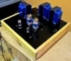
lmitche Posted July 19, 2015 Share Posted July 19, 2015 [ATTACH=CONFIG]19797[/ATTACH] Listening impressions are forthcoming... :-) Mike Hi Mike, Many thanks for the post. We are on a similar path. Your post is very helpful. Like you, I have been doing tons of research on isolation transformer safety and AC induced noise. To combat differential noise, the bond between the secondary neutral of my IS1000HS and earth ground has been restored. The Tripplite is plugged into a dedicated AC circuit. It is powering a custom 1000 watt balanced toroidal transformer designed to defeat common mode noise. This is a simple center tapped balanced toroid with no other filters. After testing many combinations, the system sounds best with the AMP and DAC plugged directly into the balanced power transformer. From the balanced transformer runs a string of 4 250 watt Tripplite transformers, all with the neutral lifted, used to power the digital front-end components. The last device on this string powers my Intel NAS running minimserver, with a SSD LPS, Harddisk LPS and a TPLINK FMC LPS. In the next position is a KECES power supply for the second FMC and SOTM SMS-100 renderer and green REGEN. The next transformer is empty and the last powers a chinese LPS for the REGEN amber. This last transformer is plugged into the balanced transformer. This string puts 4 isolation transformers between the noisy windows PC and the DAC/AMP. Having tried many other permutations, this configuration just sounds the best. My research about the safety of this configuration was in two areas. 1) The first transformer in the string is seeing the sum of the current draw from the other transformers and devices. The good news is that the thermal protection in the chain works just as intended, and was verified using a toaster as load. The circuit breakers function correctly for overload conditions. 2) After much research, it is clear that lifting the ground on the isolation transformers is a trade-off. Doing this disables the ability of a hotwire fault to chassis to be detected by the circuit breaker. The good news is, that with no reference to ground, that fault is not a shock hazard for someone touching the chassis. It is comforting to know that in 2013 US hospitals were required to place isolation transformers into service for any electrical device connected to a patient. The risk of a ground fault is especially high in operating rooms, were liquids are often on the floor. To protect patients and staff, this risk is eliminated using floating neutrals on isolation transformer. UL and international code electrical wiring standards have been modified to support isolation transformers used in this way. Anyway, this configuration just sounds great, with a much lower noise floor. It feels a bit like sculpting where the subtraction of the material (noise in this case) reveals additional details of the statue and results in a much smoother finish. Pareto Audio aka nuckleheadaudio Link to comment
lmitche Posted July 19, 2015 Share Posted July 19, 2015 Hi Imitche! I would expect you to have said: "To combat common-mode noise...", because differential noise can only reside between hot and neutral, but in any case, we agree that the first (largest) isolation transformer should have a grounded secondary. Mike Hi Mike, You may be right, that the grounded secondary eliminates common mode noise. However I have read that differential noise is created between the primary and secondary windings of the isolation transformer and that connecting the neutrals of both eliminates this differential noise, so perhaps we are both correct. Anyway, there is no doubt that the Tripplite in it's standard configuration with the balanced transformer sounds better than with it's ground lifted. Agreed it is surprising that the DAC and AMP sound better plugged into the balanced transformer, rather than having the DAC on it's own isolation transformer. One explanation could be that the amp and DAC are tightly coupled with the XLR connections, and that the extra isolation creates a ground loop or induces noise. I found a local transformer company that had built a prototype balanced transformer for audio use that never hit the market. I'll talk to them next week to learn the cost, minimum order size and lead times for an order. Perhaps we could do a group buy? Larry Pareto Audio aka nuckleheadaudio Link to comment
lmitche Posted July 30, 2015 Share Posted July 30, 2015 I haven't seen a Balanced Power solution I can afford Hi, I recently stumbled into a cache of 5 overstock audiophile 1000VA balanced power transformer units, 4 110 volt US models, and 1 230 volt European model. These units are UL and CE compliant. If you are interested PM me for details. My system has been powered by one of these for the last two weeks and you will not see me part with it anytime soon. Larry Pareto Audio aka nuckleheadaudio Link to comment
lmitche Posted July 30, 2015 Share Posted July 30, 2015 Which transformers do you have? Pareto Audio aka nuckleheadaudio Link to comment
lmitche Posted August 1, 2015 Share Posted August 1, 2015 Hi all, FYI - I just posted the details of a group buy for the balanced power supply in the Buy & Sell Audio and Computer Components forum. Pareto Audio aka nuckleheadaudio Link to comment
lmitche Posted August 2, 2015 Share Posted August 2, 2015 Thanks SandyK. Alex, let me know if you have any questions. Pareto Audio aka nuckleheadaudio Link to comment
lmitche Posted August 19, 2015 Share Posted August 19, 2015 How many VAs are you looking for? Did you see the 1000 VA European balanced power supply listed in the CA classifieds ? Pareto Audio aka nuckleheadaudio Link to comment
lmitche Posted August 19, 2015 Share Posted August 19, 2015 All the 120 volt units have been sold and delivered. The 240 volt unit is available. Please be aware it has male IEC connectors, so you may have to use adapters, or change cable ends. PM me your shipping details and I'll send you a quote, most likely tomorrow. Larry Pareto Audio aka nuckleheadaudio Link to comment
lmitche Posted August 19, 2015 Share Posted August 19, 2015 Missed that, thanks. Pareto Audio aka nuckleheadaudio Link to comment
lmitche Posted March 31, 2016 Share Posted March 31, 2016 It's a curious historical fact that piezoelectricity was first discovered using Tourlamine crystals by the Curie brothers named Jacques and Pierre. Pierre married a Polish woman named Marie, who is now known as Madame Curie. Pareto Audio aka nuckleheadaudio Link to comment
lmitche Posted April 4, 2016 Share Posted April 4, 2016 Funny, I have this exact Shunyata balanced cable connecting my DAC to Amp. I always wondered what was in the hoses. Thanks! Pareto Audio aka nuckleheadaudio Link to comment
lmitche Posted April 4, 2016 Share Posted April 4, 2016 You could use one of these to increase surface area! http://www.nofancomputer.com/eng/products/CR-80EH.php# Pareto Audio aka nuckleheadaudio Link to comment
lmitche Posted April 5, 2016 Share Posted April 5, 2016 Sam, the first Caelin patent that Jud posted shows an interconnect cable surrounded by two concentric tubes with FeSi material in the outer ring. I have a pair of Shunyata Antares cables constructed in the same fashion. Perhaps the material degrades the signal, but they sound pretty good to me. Pareto Audio aka nuckleheadaudio Link to comment
lmitche Posted November 19, 2016 Share Posted November 19, 2016 First off lets define what common mode and normal mode are. Normal mode is noise between the hot and neutral. It is assumed that you have a 50/60HZ at 120 or 240 as the "signal", so anything else is "noise" by definition. The low capacitance transformers achieve high attenuation of this noise by having very low capacitance which blocks high frequency signals, and a special magnetic circuit which is only efficient for the 50/60Hz and a couple harmonics above. Higher frequency noise does not pass through the magnetics, and they are not transferred through capacitance because it is so low. Common mode noise is noise between some other reference and the both the hot and neutral together. If this noise causes a 1V rise on the hot it will also cause a 1v rise on the neutral. Usually in three wire AC systems the "reference" for common mode noise is taken as the safety ground. A system without a secondary connection to safety ground (ie floating secondary) has essentially no coupling to safety ground so there can be pretty much any voltage between them. Any common mode noise that was on the input is blocked, but what happens on the output side is the same as just holding a piece of wire in one hand and another piece in the other hand. They are free to float all over the place due to picking up radio signals etc. So if you put a scope between safety ground and either secondary wire you will see random noise, mostly radio pickup of some sort. IF your audio equipment is designed so its input is referenced to safety ground then this may be a problem. The tie between safety ground and one of the secondary wires (secondary neutral grounding), forces them to be connected so they can't float relative to each other. If the AC for your whole audio system is connected together and run off the secondary of the transformer, then it shouldn't make any difference which way it is hooked up. BUT if you have an input which comes from a source that is not AC powered from the transformer you may find a difference in sound between the two configurations. From the safety side of things, IF you have the grounded secondary configuration then you should have a GFCI on the output of the transformer because now a sneak path can exist. John S. John, thanks so much for this amazing post. Throughout my audiophile journey there has been so much BS flying around about the AC power side of our systems that I never felt confident that I knew the right thing to do. Now I know the reasons that my setup here, achieved by listening via trial and error, is the right setup. Best, I now know the reason why! Thank you! Your simple clear and sensible explanation here should be in the best post hall of fame on every audiophile site. Well done! Larry Pareto Audio aka nuckleheadaudio Link to comment
lmitche Posted November 24, 2016 Share Posted November 24, 2016 240v here [ATTACH=CONFIG]31028[/ATTACH] though... as John Swenson suggested I better plug the JS-2 to the balanced transformer rather than straight to the power strip... I assume it's safe Hi Paolo, I would not assume it's safe just because of John's advice. John wasn't directly addressing the balanced power safety question. I'll write the manufacturer and ask them directly for feedback. Give me a few days to a week to get back to you as we are in the middle of a big holiday here. In the mean time, I would recommend disconnecting the device until we can get more feedback. Pareto Audio aka nuckleheadaudio Link to comment
lmitche Posted December 15, 2016 Share Posted December 15, 2016 I spent most of last night reading about a possible solution and came to a similar conclusion. One of the things that was blocking me was I don't know much about the handshake. I assumed that since the VBus disconnection made the DAC go dark from the computer's perspective that there would be no way to disconnect it. So today I removed the filter from my DIY cable and tested the injection of alternate power from an iPhone charger - not ideal since it's also an SMPS - put the Nano on internal battery, connected the power, then connected the computer side. Success! The highs are back in force as with the default computer connection, but without the glare, and a lot of micro-details revealed. Sweet! So we now have GND disconnection + VBus disconnection. YashN, I am running my microIDSD with an AQVOX cable injecting power from an LPS1. This way I don't need to use the internal battery power. The shield needs to be connected to the source computer for handshake. I have yet to try disconnecting ground once done. It sounds fabulous! Pareto Audio aka nuckleheadaudio Link to comment
lmitche Posted December 15, 2016 Share Posted December 15, 2016 I was just on their website yesterday again and the iDSD Nano is in the supported DAC list so I figured I could try my experiment today. Interesting info about the shield though. I suppose if the shield is disconnected then the DAC wouldn't be recognised at all. I do have a future experiment with modified shielding planned. Would you say the LPS-1 sounds better than the internal battery? Enjoy! I have a listening session today on just this topic. More later. Pareto Audio aka nuckleheadaudio Link to comment


Recommended Posts
Create an account or sign in to comment
You need to be a member in order to leave a comment
Create an account
Sign up for a new account in our community. It's easy!
Register a new accountSign in
Already have an account? Sign in here.
Sign In Now