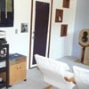
Popular Post Superdad Posted August 4, 2018 Popular Post Share Posted August 4, 2018 One of the challenges of prototyping new circuit designs in the era of surface-mount parts--many of which are incredibly tiny or have many pins/pads underneath which can not possible be hand soldered even under a microscope--is that sending out every prototype board to be assembled by giant production pick-and-place machines is very expensive and chews up extra weeks. We have often spent $2,000-$3,000 to have 3 samples of a design produced--only for those boards to end up on the scrape pile a couple weeks later. The sort of projects John works on are with 4-layer boards with multiple ground domains and lots of impedance-controlled traces. Hand-prototyping is simply impossible. John already has a small vapor-phase-reflow oven (vapor phase soldering is fascinating too--Google it) that uses $800/quart liquid, so when he gets bare prototype PCBs made (along with a stencil), he can spread the solder paste and hand-place many parts. But for a complex design it can take 7-10 hours of tedious time under a microscope to place the tiny parts with tweezers--and he has to hope he does not place an incorrect part and that he gets done before the solder paste is no good. Prior to his move to Washington State (guess it's been over a year now), he started assembly of a complicated kit for a prototyping pick-and-place system called Lite Placer (www.liteplacer.com). It came in 1,000+ parts with very detailed instructions, but still it required engineering of motor control systems, lots of custom wiring, and of course weeks of hair pulling. Here is how it started: His move necessitated it being packed up, and once he set up his fancy new lab (quartz countertops, low-voltage lighting designed not to interfere with sensitive measurements, and lots of cool new test gear) there was a backlog of projects to finish for UpTone and Sonore. Still, he managed to squeeze in time to complete the beast. Here are a couple of shots during that: I have no idea how many weeks he spent on this--or how many times he called to tell me he forgot to include one or two more sets of control wires in the cable track. And even once assembly was complete there was days of work (and a lot of FedEx packages from the developer in Finland) with calibrations, getting the vacuum pick-up tools working right, and making parts-tape-strip holders (think he used his GlowForge laser cutter for those). At long last it lives and works fabulously! I'm sure John will chime in with other details and to answer questions, but for now here are photos of the incredible machine and a video of the first full board place he did. He got it done just in time as he has actual project boards waiting to be assembled. Enjoy. And congratulations to John! P.S. What sounds like a goat in the video is the vacuum pick-up tool in action. So my nickname for the beast is "The Goat." RichB, Cornan, elcorso and 4 others 4 3 UpTone Audio LLC Link to comment
RichB Posted August 4, 2018 Share Posted August 4, 2018 Wow! Very cool! My inner engineer is geeking out! ? Hmmmmmm . . . Looks like it could be a protype Ethernet switch board in the vid. ? --------------- Rich Brkich Owner, Signature Sound Liverpool, New York USA Website: http://www.sigsound.com FaceBook Page: http://www.facebook.com/Signature.Sound.HiFi Link to comment
rickca Posted August 5, 2018 Share Posted August 5, 2018 This video is responsible for a 43% drop in box office for Mission Impossible: Fallout from its opening weekend. Pareto Audio AMD 7700 Server --> Berkeley Alpha USB --> Jeff Rowland Aeris --> Jeff Rowland 625 S2 --> Focal Utopia 3 Diablos with 2 x Focal Electra SW 1000 BE subs i7-6700K/Windows 10 --> EVGA Nu Audio Card --> Focal CMS50's Link to comment
Superdad Posted August 5, 2018 Author Share Posted August 5, 2018 7 minutes ago, rickca said: This video is responsible for a 43% drop in box office for Mission Impossible: Fallout from its opening weekend. Really? Then the new MI movie must be very boring in comparison because even I couldn’t watch more than about 6 minutes of John’s 20 min. placer video without skipping ahead. Spoiler alert: The parts all get placed and the machine stops at the end! No Marvel teaser trailer after the credits. UpTone Audio LLC Link to comment
asdf1000 Posted August 5, 2018 Share Posted August 5, 2018 Forget making any products - just putting that thing together by himself (with only phone/email/FedEx help?) is an achievement! Congrats. Link to comment
Superdad Posted August 5, 2018 Author Share Posted August 5, 2018 3 minutes ago, Em2016 said: Forget making any products - just putting that thing together by himself (with only phone/email/FedEx help?) is an achievement! Yeah, no kidding. And a lot of what you see—the large cable track, the wiring, and the chassis and connectors for the control circuitry—did not come with the kit. John also built a small CNC mill (in the garage ‘cause that’s messy!) and got a sheet metal bending break to make the aluminum chassis. Of course those tools will come in handy for other projects. asdf1000 1 UpTone Audio LLC Link to comment
asdf1000 Posted August 5, 2018 Share Posted August 5, 2018 Just now, Superdad said: Yeah, no kidding. And a lot of what you see—the large cable track, the wiring, and the chassis and connectors for the control circuitry—did not come with the kit. John also built a small CNC mill (in the garage ‘cause that’s messy!) and got a sheet metal bending break to make the aluminum chassis. Of course those tools will come in handy for other projects. Very nice indeed. If only I had half the talent of that man ? Looking forward to the new projects. Link to comment
Popular Post JohnSwenson Posted August 5, 2018 Popular Post Share Posted August 5, 2018 4 hours ago, RichB said: Wow! Very cool! My inner engineer is geeking out! ? Hmmmmmm . . . Looks like it could be a protype Ethernet switch board in the vid. ? I was wondering if anybody would notice that! Yep, this board is a switch test board. It doesn't have any of the special magic sauce, just testing out the functionality. As shown it took about 20 minutes to place the parts, and about an hour to put all the pieces of tape on the parts boards and setup all the tapes in the software. So about an hour and twenty minutes from opening parts box from Digikey to placed board. Versus about 6 hours under a microscope with tweezers. Being able to do this totally changes what I am willing to do myself, the big boards just take so long to do and are very difficult to do, (you can't stop and take a break, you have to get it done while the solder paste is still good). Now I'm willing to take on quicker turn arounds and explore more things. It was a lot of work to get done, but it finally works great now. John S. Jud and Superdad 1 1 Link to comment
Popular Post JohnSwenson Posted August 5, 2018 Popular Post Share Posted August 5, 2018 Some general words on the LitePlacer. First off the designer (Juha) is VERY responsive to questions and the times I had some bad parts he shipped them overnight international FedEx without charging me anything! This is a daunting kit, there are a LOT of parts as you can see in the pictures, but Juha has written incredibly detailed instructions. He designed the whole thing in 3D CAD and includes exploded 3D renderings of every step it is not hard to follow, just a LOT of it! Part way through the construction he came out with a major upgrade, an automatic nozzle changing system, I was getting to the step where that needs to be installed, so I ordered the upgrade kit and tried to install it. The nozzles are held in some slots by magnets with holes in them, in some of my magnets the holes were too small. He checked his stock and found a few percent WERE undersized, he sent me some new ones, but I had to pack it all up for the move before I got it all assembled. Unfortunately it was Almost a year later before I could start working on it again. The holder went together great now, but the nozzles would not go all the way on the shaft! I fussed with it for weeks and could not get it to work. Juha sent me a new set of nozzles but they didn't work much better. He then decided to check his stock and found that 20% of his stock didn't fit either. SO now hew checks every single one before he sends them out, while he is trying work with his supplier to fix the problem. Even with the third set I still had problems, but I did get them to work by modifying some software parameters (push harder) This design has a camera that figures out exactly where the parts are in a tape by looking at the holes in the tape, and looking at fiducials on the boards (little circular pieces of copper), with this it can build precise coordinate systems between the tapes and the locations on the board. This allows it to have an inexpensive mechanical system that is not the best on the planet, the camera takes care of a lot of the slop in the mechanical system. The kit comes with the controller board but no power supply or case for the board, or any wiring. The instructions make a great deal about using shielded cable and grounding the shield to keep radiated noise from the motor controllers from messing up the camera, USB lines, computer etc. Being me I decided to use starquad cable and JSSG (which works great BTW). I used Canre starquad microphone cable since it is very flexible, but it took two cables per motor to do this. When I was installing the wiring I found he recommended cable chains did not works, that large amount of microphone cable would not fit! So I needed to buy some much bigger cable chains to hold all this wire. (one of the pictures is putting all the cables through the cable chain) The instructions say the controller board can get hot so it needs an enclosure with a fan, being the weird guy I am, I decided to use a thermal chimney instead. So instead of the board laying flat, I have it vertically oriented in a case which forms a thermal chimney that creates its own air currents effectively cooling the board without a fan. So I used a CNC router to mill out the "D" holes for the connectors and a laser cutter to cut out the acrylic cover and a 3D printer to make the "feet" that holds the assembly up off the table so air can get in underneath. This thermal chimney works extremely well, the board just barely gets warm at full motor current. I also used the laser cutter to make the "parts boards", I engraved the "ruller" on the board for each tape position. This means I only need to work out the position of the tape once,. With the board I can setup a set of tapes in advance over at the bench where it is easier to do than on the placer itself. I'm using repositionable adhesive spray to keep the tapes stuck to the board. The software figures out the parts locations by looking at the holes in the tape, this is easy for white tape and even easy for black tape, but some parts come in clear tape, this was NOT easy, there is almost no contrast between the tape and the hole. I eventually got it to work by using a black background under the holes and setting up the light for the camera so it reflects off the surface of the clear tape, this gave enough contrast so the software could reliably find the hole. This took a lot of work to get built and working properly, Juha gave fantastic customer support, I eventually got it working well, it was definitely worth it. John S. auricgoldfinger, Jud, Cornan and 3 others 3 3 Link to comment
jamesg11 Posted August 5, 2018 Share Posted August 5, 2018 Astonishing! Is there a DIY level higher than this? Unlikely ... macmini M1>ethernet / elgar iso tran(2.5kVa, .0005pfd)>consonance pw-3 boards>ghent ethernet(et linkway cat8 jssg360)>etherRegen(js-2)>ghent ethernet(et linkway cat8 jssg360) >ultraRendu (clones lpsu>lps1.2)>curious regen link>rme adi-2 dac(js-2)>cawsey cables>naquadria sp2 passive pre> 1.naquadria lucien mkII.5 power>elac fs249be + elac 4pi plus.2> 2.perreaux9000b(mods)>2x naquadria 12” passive subs. Link to comment
4est Posted August 5, 2018 Share Posted August 5, 2018 10 hours ago, JohnSwenson said: This design has a camera that figures out exactly where the parts are in a tape by looking at the holes in the tape, and looking at fiducials on the boards (little circular pieces of copper), with this it can build precise coordinate systems between the tapes and the locations on the board. This allows it to have an inexpensive mechanical system that is not the best on the planet, the camera takes care of a lot of the slop in the mechanical system. Would this be why the x-y travel has a lil "overshoot"? I was going to suggest tuning your drives otherwise. Congrats btw. After having to rebuild an antique 3 axis CNC router, I can appreciate the amount of effort this takes. Jud 1 Forrest: Win10 i9 9900KS/GTX1060 HQPlayer4>Win10 NAA DSD>Pavel's DSC2.6>Bent Audio TAP> Parasound JC1>"Naked" Quad ESL63/Tannoy PS350B subs<100Hz Link to comment
look&listen Posted August 5, 2018 Share Posted August 5, 2018 9 hours ago, JohnSwenson said: This design has a camera that figures out exactly where the parts are in a tape by looking at the holes in the tape, and looking at fiducials on the boards (little circular pieces of copper), with this it can build precise coordinate systems between the tapes and the locations on the board. This allows it to have an inexpensive mechanical system that is not the best on the planet, the camera takes care of a lot of the slop in the mechanical system. What are dimensional tolerances for this mechanical system, & placement requirements ? 9 hours ago, JohnSwenson said: Being me I decided to use starquad cable and JSSG Forget just what "JSSG" stands for, but not named by you so ridiculous name not your fault. I only use name "JSSS" for "John Swenson Shorted Shield". JSSS makes sense to me to describe configuration. Will not use other name. Maybe that make sense to you too? 9 hours ago, JohnSwenson said: I used a CNC router to mill What brand/kind of CNC machine? Do you need to monitor placer activity? I would not want to be in same room with machine noise for much time, ugly sound. Also works slower then anticipated. Maybe from seeing pro machines move faster then eye can follow. Thx for good pictures & details of great DIY project. Almost want to do one too Link to comment
JohnSwenson Posted August 6, 2018 Share Posted August 6, 2018 13 hours ago, 4est said: Would this be why the x-y travel has a lil "overshoot"? I was going to suggest tuning your drives otherwise. Congrats btw. After having to rebuild an antique 3 axis CNC router, I can appreciate the amount of effort this takes. The "overshoot" is backlash compensation, there is a little bit of slop in the mechanical system, in order to compensate for that all moves go in to rest from the same direction, it moves to a slight offset from the final position, then does a separate small move to the final position, this move is always in the same direction and speed. This dramatically improves accuracy. John S. Link to comment
Popular Post JohnSwenson Posted August 6, 2018 Popular Post Share Posted August 6, 2018 10 hours ago, look&listen said: What are dimensional tolerances for this mechanical system, & placement requirements ? Forget just what "JSSG" stands for, but not named by you so ridiculous name not your fault. I only use name "JSSS" for "John Swenson Shorted Shield". JSSS makes sense to me to describe configuration. Will not use other name. Maybe that make sense to you too? What brand/kind of CNC machine? Do you need to monitor placer activity? I would not want to be in same room with machine noise for much time, ugly sound. Also works slower then anticipated. Maybe from seeing pro machines move faster then eye can follow. Thx for good pictures & details of great DIY project. Almost want to do one too The actual measured accuracy is around 0.03mm with backlash compensation turned on, with it turned off it is much worse, but faster. The requirements are that both pins of an 0402 component touch solderpaste, 0.03mm is more than enough to achieve this. In reality not every component gets placed correctly, on this board three parts wound up with only one pin touching solder paste. This happens to other people as well, there is a lot of speculation and testing on this, it seems to be that the parts move on the nozzle as they undergo acceleration and deceleration. I slowed down the acceleration a lot from what it can do to improve this as much as I can. Speculation is that we need to use a more powerful vacuum pump, but then the whole vacuum system has to be tweaked including the solenoid valve and tubing sizes etc. Other options are looking at maybe working on the surface of the nozzle, but every attempt so far has serious downsides so I just left that alone. JSSG stands for John Swenson Shielding Guidelines. I did not come up with it. I'm terrible with names. It is sold by an individual: Juha Kuusama . The website is liteplacer.com. He designed the whole thing, wrote the instructions, puts all the kits together himself and does all customer support. Amazing for one guy, I don't think he ever sleeps. He did take a vacation once. I do watch it while it is doing its thing, it really isn't as noisy as it sounds in the video, that was the AGC in audio channel of the camera. The vacuum pump is the noisiest part of the machine, some people use a different pump that doesn't make as much noise. I do monitor it, with my hand near the big red button, the first couple times I tried it out it did some strange things. They all turned out to be operator error, things like a tape being vertical on the board but the tape descriptor saying it was horizontal, things like that. Once I get all the descriptors right it does what it is supposed to. This is an $1800 kit, not a $100000 pro machine, yep it does not run as fast. But it is for one off prototypes, not high volume production. I'm actually running it quite a bit slower than it CAN run in order to try and increase the accuracy. I'm fascinated watching it doing its thing, knowing that I'M not over a microscope for hours doing it myself! One guy built one in 4 days, but most people take several months to get one built, it took me almost 2 years, but there was a 1 year hiatus, which was a good thing, Juha improved the design a lot over that period of time. For me, definitely worth it. John S. Superdad, asdf1000, motberg and 4 others 5 2 Link to comment
PeterSt Posted August 7, 2018 Share Posted August 7, 2018 @JohnSwenson, nice work ! Em, here is ours ! I'm afraid this is in a hiatus of two years by now. It is up to the stage of connecting the MCU and get it going for real. If someone motivates me to sell it, then, well ... asdf1000 1 Lush^3-e Lush^2 Blaxius^2.5 Ethernet^3 HDMI^2 XLR^2 XXHighEnd (developer) Phasure NOS1 24/768 Async USB DAC (manufacturer) Phasure Mach III Audio PC with Linear PSU (manufacturer) Orelino & Orelo MKII Speakers (designer/supplier) Link to comment
Middy Posted January 1, 2019 Share Posted January 1, 2019 Top off the line are probably the phone makers P+P machines. Those things are monsters placing hundreds of parts per min. Running these is a full time job set ups change overs programming....glad i dont run them anymore. Hats off to you, hand placing a full board is a pain, soldering the lot worse... Good luck as always.. Dave Link to comment


Recommended Posts
Create an account or sign in to comment
You need to be a member in order to leave a comment
Create an account
Sign up for a new account in our community. It's easy!
Register a new accountSign in
Already have an account? Sign in here.
Sign In Now