zilch0md Posted July 9, 2015 Share Posted July 9, 2015 Hey YashN, I'm in research mode, too, so by all means, please post any link you feel makes a contribution to this topic. I'm sure you would join me in eagerly welcoming any constructive criticism of incorrect information we might dig up along the way, from subscribers who are willing to charitably and patiently guide us toward the truth. Mike Link to comment
zilch0md Posted July 10, 2015 Share Posted July 10, 2015 I hope this guy isn't floating his secondary... Link to comment
zilch0md Posted July 10, 2015 Share Posted July 10, 2015 My research on isolation transformers has left me with two unanswered questions: 1) Would I be better off buying a multi-outlet isolation transformer with a VA rating that's just sufficient to cover the combined load of all of my components, or should I buy several smaller isolation transformers - one for each component? Superdad has written that he uses multiple "smallish" isolation transformers at each load. One and a half has written that he uses a 2KVA isolation transformer ahead of his Equi-Tech balanced transformer, but laments that it offers a greater capacity than is ideal, suggesting that as the VA rating of an isolation transformer rises relative to the load it serves, the impedance is reduced and you start to lose the current-smoothing benefits. I'm paraphrasing, but he suggests that going much higher than 2x the load you will lose this benefit. In my case, a DAC and headphone amp, plus a small TeraDak LSR to power the USB Regen and DAC, will only pull a maximum of 46VA at 110V. How many Watts is 46VA? For that we need to know the Power Factor (PF), but let's assume it's 0.8. P(W) = S(VA) × PF 46 VA * 0.8 = 36.8 Watts So, if there's some truth to One and a half's statement (and I have no reason to doubt him as he seems to be very well versed on this stuff), even if the Power Factor were 1.0, I should avoid isolation transformers rated higher than 2x 46 Watts = 92 Watts. In other words, my loads total something less than 46W, but I'm using a 500W (110V) isolation transformer, which can handle more than 10x the total load - and thus, could be operating at too low an impedance, which translates to greatly reduced, possibly non-existent, current-smoothing benefits). Would I be better off with a smaller single isolation transformer (no more than 2x 46W, no more than 2x my total load), or perhaps multiple, even smaller, isolation transformers (with each of them rated at no more than 2x the individual loads)? 2) Should I purchase isolation transformers that float the secondary or isolation transformers that ground the secondary's neutral? All Tripp-Lite isolation transformers are designed with the secondary's neutral grounded - not floated. Superdad and One and a half have both written that their isolation transformers have floating secondaries. Indeed, I've found several references where "audiophiles" are saying that an Isolation Transformer should float the secondary, that its neutral should not be connected to ground. (Neither lead of the secondary should be connected to ground.) It is almost universally claimed that this will reduce noise coming in from the mains. And I've also found several "non-audiophile" references where floating the secondary is said to provide greater safety (to the equipment that's plugged into the isolation transformer). Whether the protagonists of floating an isolation transformer's secondary are audiophiles interested in improving sound quality or non-audiophiles interested in protecting their oscilloscopes, for example, the majority of them agree that as long as there's a chassis-grounded Faraday shield between the primary and secondary windings, there is a very, very low risk of shock. You would have to touch both the hot and the neutral of the secondary, as touching one or the other provides no path for current to flow through your body. Now here's the weird thing: I can also find several audiophile and non-audiophile references, where it's said that grounding the neutral from the secondary will reduce common mode noise. This leaves me in a quandary because reducing common mode noise by grounding the neutral of the secondary coil seems to be something every audiophile would want, and yet, floating the secondary is what most audiophiles seem to prefer, claiming that doing so reduces noise from the mains. Imitche has written (joining what seems to be a majority consensus) that even though floating the secondary comes at the expense of no longer enjoying common mode noise rejection, there are many audible benefits that outweigh the loss of common mode noise rejection. All opinions and discussion and links to articles relating to these two questions would be very much appreciated! Thanks! Mike Link to comment
zilch0md Posted July 12, 2015 Share Posted July 12, 2015 Hi Mike, While I can't address your first question, research on the second question continues. There is no question in my mind that floating the ground on my Tripplite isolation transformer has yielded a terrific increase in sound quality. My ears don't lie. However, there is no doubt that this modification is dangerous, but how dangerous, and is there a way to add devices that reduce that danger? As a boat owner, I spend a lot of time at marinas. Did you know that most marinas have isolation transformers at each slip that float the neutral prior to the AC connection point to the boat? Essentially this removes the earth ground reference and prevents current from flowing in the water when ground faults occur in onboard devices. I have found several heartbreaking stories of children swimming off boats in a marina that were killed due to the lack or improper wiring of these isolation devices. Here is an example of one of these marine isolation transformers from a nearby manufacturer: Marine Isolation Transformers Standby power generators are by nature not connected to earth ground. Neither are the many 2 wire AC devices in a home, I have plenty. I am not advocating that anyone duplicate what I have done. However the magnitude of the risks are still unclear to me, and there appear to be examples were floating or eliminating the neutral from earth ground is best practice. So there is more to learn about the risk/benefit ratio here. The benefit is real, the risk and our ability to manage it is still unknown to me. Stay tuned. Larry Thanks very much for your reply, Larry! You do seem to be among a large majority who prefer the sound of isolation transformers with floated secondaries, whether they are purchased in that state or modified (by competent users). Everyone should feel free to scold me if they feel I'm failing to warn mothers to remove the baby before folding the stroller and tossing it into the car, but the isolation transformers that are designed and shipped with floated secondaries don't appear to be illegal in any way and several improbable yet certainly possible equipment failures would be handled by a grounded Faraday shield that separates the primary and secondary coils (which also reduces normal mode high frequency noise). There is always, of course, a risk when making changes to gear. So, I appreciate and concur with your perspective there. I've not yet tried the mod myself (with my Tripp-Lite is500), as I'm still thinking of using smaller "floated secondary" isolation transformers at each component. Look for Russ57 on audioasylum and the tweaks section, where he writes on getting a big transformer and then de-rate it for use. 1.5 probably didn't spend a lot of time researching about proper transformers to use or how to use them. (snip) Hi YashN, I managed to find this post by Russ57: I use one 5kva for all my analog and one 2.5kva for all the digital with individual small isolation transformers afterwards. Remember when wired for balanced power in most cases you have to derate by 50% and I also like to make a transformer's volt-amp rating twice what the equipment draws. Which basically adds up to needing a transformer 4 times as large as what you might think is needed. I'm not using balanced power, so I'm going to assume Russ57 would advise me to start with an isolation transformer rated at twice the total VA needed by all of downstream gear, but with smaller isolation transformers inserted ahead of each digital component. And I will assume he would say that each of the individual isolation transformers should offer twice the rating of the component served. Here's another golden nugget from Russ57 at AA: Okay, first off ALL transformers are "isolation" transformers unless they are an autotransformer. On any transformer you could bond the secondary, at some point, to ground. It is up to you to decide if that is best for your purpose. One thing to keep in mind about "balanced power" is that one of it's goals was to meet with approval from NEC-(national electrical code). So with that goal in mind it was necessary to ground the center tap because code would never allow an unreferenced power supply system. Code calls for separate dedicated panels with double pole breakers but useing the same ground as all the other electrical systems. Having the reference to ground at the center tap and having equal voltage at each outout relative to ground also allows the loads to cancel out, assuming they are equal. If your isolation transformer has no center tap provision then you can't turn it into a balanced power transformer. Now don't get depressed as an isolation transformer will help improve your sound just not as much as a balanced power one might be able to. You could ground either side of your secondary if you wished to or you could leave it floating. I would consider it safer to ground one side but you may decide that you wish to isolate your equipment from ground assuming you have two wire power cords. Just be aware that most equipment would normally only switch and fuse one wire, the hot, and with a floating secondary, and balanced power for that matter, you really end up having two hot wires and no neutral wire. That is why code calls for double pole breakers with balanced power distribution systems. I think it is article 940 if you care to look it up. The cheapest way to get balanced power that I know of is to pick up a 480/240 by 240/120 single phase transformer. Get a decent size one, say 2-5 KVA because it's rating will be cut in half. Wire the primary for 480 VAC but feed it with 240 VAC and wire the secondary for 120 VAC and ground the secondary at the X2 & X3 junction. This way you should end up with X1 & X4 each measuring 60 VAC to ground but 120 VAC across them. Try to find a transformer that has a "Faraday" or electrostatic screen that gets bonded to ground. The closer X1 & X4 measure in value the better. That is better each measure 60 VAC to ground than one measures 70 VAC and one measures 50 VAC. Get the pic? Russ PS Put a regular 100 watt light bulb on your transformer secondary when you take voltage measurements as it needs some load. And just one more from Russ57: (snipped a lot of good stuff about building your own balanced power supply) Now what about the digital? Well ideally you'd have a second balanced power transformer sized and wired as per above. But even more importantly, you must have individual isolation transformer (in addition to and after the second digital only balanced transformer) for each and every digital item (signal transformer makes great ones at a reasonable price)...DAC, CD, DVD, CDRW/burner...sorry but dem's the facts. This is more important than having a balanced power transformer for the digital stuff if you only have one digital item then balanced power serves both needs. To further improve the whole deal I strongly encourage the use of Jon Risch's excellent filter (properly sized and operated between the min and max current and yes there is a min)in front of each of the balanced power transformers. Now would I do this if I had to pay hundreds of dollars per transformer...no I couldn't afford it. But would I say it is worth it....absolfreakinglutly (I have 5 transformers)! Simply put you haven't heard a dead quite black background without one. You truly can't tell anything is on....even on phono and volume fully ranked....no hum no buzz...and the isolation of the digital totally eliminates a high hertz artifact you didn't know was there and causing listening fatigue. No, I'm not employed by a balanced power company:) Enjoy. Russ You've been doing your homework YashN and I very much appreciate your having introduced me to Russ57's writings! And Superdad is onto something, having put "smallish" isolation transformers in front of each of his source components. Unfortunately, I'm incapable of building my own gear, which begs the question: Where can I find a ready-to-use 110V 30VA isolation transformer with floating secondary (as the individual transformer for my max. 15VA DAC) and a ready-to-use 110V 60VA isolation transformer with floating secondary (as the individual transformer for my max. 30VA headphone amplifier)? The B&K Precision 1604A is about the smallest ready-to-use isolation transformer I can find that's documented as having a floated secondary. But fi there's any significance to Superdad, One and a half, and Russ57 keeping the VA rating down, this B&K 1604A is still rated way too high, at 175VA, for individual use with my 15VA DAC and 30VA headphone amp. At 175W would be 175VA assuming a power factor of 1.0, or 219VA assuming a power factor of 0.8 - which is 14.6x (not 2x) the load of my DAC and 7.3x (not 2x) the load of my amp. One and a half wrote (I'm paraphrasing) that keeping the VA rating of the isolation transformer below 2x the load allows the benefit of smoothing "current lumps." And Russ57 also seems to think that a 2x multiplier is ideal (4x for balanced power.) There may still be some benefits to be had just by individually isolating the digital components, however. Opening my Tripp-Lite is500, I can addition to seeing the grounded neutral of the secondary, I can see that all four outlets are connected - they are not isolated from each other in any way. (snip) The differing opinions are interesting. The way I'd approach it if I could would be to test with two iso transformers, one with float and another one without, listen for the auditory changes with a cheap component, e.g. an old CD player. If the benefits of the float do seem something to pursue in a more permanent manner, I'd continue to research for a way of making it safe for the end-user (if at all possible). If the results are close, you're safe not floating anything. Given how there are some UL-approved, 3-prong outlet, isolation transformers available with floated secondaries, I'm thinking of adding a SPST switch to my Tripp-Lite is500, to open the grounded neutral of the secondary, at will. I am not advocating that anyone else modify their equipment. When I electrocute myself, consider it to have been for your entertainment purposes only. Further research brought me once again back to Jon Risch over at AA. He's awesome. (snip) Thanks YashN! Link to comment
zilch0md Posted July 12, 2015 Share Posted July 12, 2015 Remember that to become a true Darwin Award candidate you have to say, "ya'll watch this" right before you flip the switch Good one! :-) Link to comment
zilch0md Posted July 13, 2015 Share Posted July 13, 2015 Thanks again, YashN. (snip) Jon Risch has more on the iso transformers: he also advises smaller ones for the digital components. Bear in mind that at the time on AA, these pursuits were for a system where the CDP reigned king as a digital source. Over here, at CA, we need to transpose that to the computer as digital source, and check power rating. (snip) I'm off to check out your Jon Risch lead. I plan to stay open-minded, of course, as I dig deeper into isolation transformers, but for now, as an experiment, I've ordered the B&K Precision 1604A (175W, single-outlet, with grounded Faraday shield and floating secondary terminals) to go between my unmodified Tripp-Lite is500 (500W, four-outlet, with grounded Faraday shield and a grounded neutral on the secondary) and my DAC (Metrum Acoustics Octave MkII). My (eager to be corrected) understanding at the moment is that the grounded neutral on the secondary of the Tripp-Lite is500 will provide common mode noise rejection that I would forfeit if I modified the is500 to float its secondary. The downstream B&K Precision 1604A, with its factory-designed floating secondary, will provide normal mode noise rejection that's not available with the grounded secondary of the is500. The USB Regen + USB 2 module of my DAC are now getting their power from an Anker Astro 3 LiPo battery, set for 9V output, so there's no need to get a second B&K 1604A unless or until I purchase the 217-part UpTone mystery device or I decide to use some other LPS that's superior to what I'm hearing with my 9V battery pack. My USB source is an iPad 3 > CCK > Supra cable, so there's no chance of a ground loop there either, as the iPad 3 is battery-powered when playing. The only other cables leaving the DAC are the RCA interconnects to my headphone amp, but I can't imagine a need to buy a two-channel RCA (line level) isolation transformer (like the Jensen IsoMax CI-2RR), because there's no path for ground loop currents to flow, when both the Regen and the iPad 3 are powered by independent batteries, and the DAC itself is powered by the floating secondary of a B&K 1604A. What do you think? :-) If the high ratio of transformer capacity to load is an issue, I might lose some benefits (current-smoothing?) that I wouldn't lose if I could get the transformer ratings down to 2x the load, but I'll start with this setup and see what I can hear. In any case, the USB Regen has taught me (like nothing else) that digital noise is insidious for how easily it can be overlooked. I've awakened to the fact that I should never assume "I have arrived" in terms of noise reduction and thus, the old adage simply does not apply: "Don't fix what ain't broken." Nope. I want to keep right on "fixin' what ain't broken" (wallet permitting) until the fixes prove themselves useless. :-) Mike Link to comment
zilch0md Posted July 14, 2015 Share Posted July 14, 2015 I did the same thing with 2 knitting needles. I was not allowed to repeat that experiment! When I was about 25, I accidentally directed a column of water coming from a garden hose right into a 120V AC outlet. I had bare feet on wet concrete. The garden hose was in my right hand. I went stiff and fell backward like a plank onto the grass next to the driveway, breaking the connection. The most amazing thing was that for several hours following this inadvertent electro-therapy, my thoughts were very clear and focused. Seriously, I should have tried writing some music or poetry or doing some sculpture! And then my brain got cluttered again. LOL :-) Link to comment
zilch0md Posted July 14, 2015 Share Posted July 14, 2015 (snip) Let us know the outcomes of your experiments too! Thanks for all of your feedback, YashN. Not owning a balanced power solution, myself, I cannot say that I've done any testing with them, but I'm becoming increasingly convinced from a lot of reading, that properly arranged isolation transformers can do a lot more for noise reduction than just preventing ground loops. More to follow, later... :-) Mike Link to comment
zilch0md Posted July 17, 2015 Share Posted July 17, 2015 This is where I'm headed - from reading everything I can find on isolation transformers ... At this point in my experimentation, I'm running into a problem with these allegedly 1:1 transformers not being 1:1. I'm experiencing as much as a 6.5% increase in voltage with one of them (from input to output). So some returns or exchanges are in order and/or I will just drop a Variac Transformer in front of the whole mess to bring the voltage down at the start of the chain. I'm measuring 120.4V at the mains, currently. I'm not going to plug in any gear and have a listen if I can't keep the voltage below 125.0 More later... Mike Link to comment
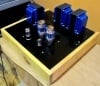
zilch0md Posted July 18, 2015 Share Posted July 18, 2015 Like minds, like minds, Mike. Gathering a lot of info so that it all clicks into place in my mind at one point. The graphic looks great, I was thinking of ding some as well. Keep it up! Thanks for your encouragement, YashN. :-) Here are some details of what I'm finding under the leaf litter in the forest of isolation transformer articles I've read... First, the text of an email I had sent to B&K Precision regarding their 1604A 175W Isolation Transformer (with floating secondary): JUL 16, 2015 | 07:29PM PDT Original message I have a brand new 1604A delivered by Amazon today. Specifications say "Output Voltage: 117 to 124 V nominal (120 V input)", but with two different meters I'm measuring output at 7.8V greater than input, when specs indicate it will be no more than 4V greater. For example, with 120.4V input, I'm getting 128.2V output. Do you consider this to be "working as designed?" Should I return it for exchange? Thanks! Mike And here's the response from a B&K Precision support rep: JUL 17, 2015 | 11:55AM PDT Mike, Yes, the output of this unit is rated at 117 to 124 V “nominal” meaning it can go a bit high and a little bit down and that is part of its normal operation. (snipped his recommendation of their variable AC power supplies) However, going back to your main concern, the unit is performing as it should. Usually, when the unit is not loaded, it is preferred to have a little higher voltage than the nominal, this is to provide all the voltage when the unit gets loaded. (snip) His last paragraph (that I've bolded, above), about how the voltage will come down when the transformer is loaded (up to 175 Watts), has proven to be a true statement. Note, that the B&K Precision 1604A is rated to handle up to 175W. Just now, I took these measurements with a Kill-A-Watt P3: Measurements: [TABLE=width: 500] [TR] [TD]Mains voltage (wall outlet)[/TD] [TD]122.0 V[/TD] [TD][/TD] [/TR] [TR] [TD]B&K 1604A with no load[/TD] [TD]130.4 V[/TD] [TD]+6.89% relative to mains voltage[/TD] [/TR] [TR] [TD]B&K 1604A with 100W light bulb[/TD] [TD]123.9 V[/TD] [TD]+1.56% relative to mains voltage[/TD] [/TR] [/TABLE] Estimates: [TABLE=width: 500] [TR] [TD]B&K 1604A with 175W light bulb[/TD] [TD]119.0 V[/TD] [TD]-2.40% relative to mains voltage[/TD] [/TR] [TR] [TD]B&K 1604A with 160W light bulb[/TD] [TD]120.0 V[/TD] [TD]-1.64% relative to mains voltage[/TD] [/TR] [TR] [TD]B&K 1604A with 145W light bulb[/TD] [TD]122.0 V[/TD] [TD]0% relative to mains voltage[/TD] [/TR] [/TABLE] Thus, with a 145W load, the B&K Precision 1604A would output the same voltage as its input voltage. That's just the result of their design choice. Problem: The Kill-A-Watt P3 says my DAC only pulls 7.6W (70mA) - so, still without actually plugging my DAC into the B&K 1604A, I've calculated that the load presented by my DAC would only bring the 1604A output voltage down from 130.4V to 129.9V - still too high for my peace of mind! I don't want to exceed 125V. Apparently, this is just the nature of unregulated inductive energy transfer between two (1:1) coils - the efficiency drops as the load increases. I'm startled that I'm having to figure this out on my own after all the reading I've done about isolation transformers. You would think that someone, somewhere, would have mentioned this in the articles they've written about isolation transformers. Perhaps the authors I've been reading simply don't know this (or they assume that every reader does), but the voltage increase can be bad news if you use an oversized transformer for your load, which everyone seems to universally recommend. And if you start daisy-chaining your isolation transformers (with those having grounded secondaries preceding those with floating secondaries), with each of them being oversized, it gets even worse. My Tripp-Lite is500 demonstrates a no-load voltage increase of 2.57%, which is a lot better than the 6.89% no-load increase of the B&K Precision 1604A, but it only means that Tripp-Lite optimized the is500 for a load that's about in the middle of its rated 500W capacity, rather than optimizing for a load that's closer to the maximum. With no loads, I just now measured a whopping 134.3V at the (floating secondary) B&K 1604A when it is daisy-chained off of the (grounded secondary) Tripp-Lite is500 - as I intend to use it (for both common-mode and normal-mode noise reduction). That's 134.3V from a mains voltage of 121.7 V, at the moment - a 10.4% increase! And I can't expect that voltage to drop by much under load with my DAC and headphone amp together pulling only about 25W. If I was ill-informed or simply rash enough to plug them in now, I calculate I'd be hitting the DAC with 133.8V. No thanks! And thus, later today, Mr. UPS will be delivering an APC LE1200 Line-R 1200VA Automatic Voltage Regulator. Only $46.52. (Big spender!) It has a three-position switch on the back that allows you to select your choice of three regulated output voltages: 110, 120, or 127V. I'll be setting that to 110V, which I've calculated will give me a very comfortable, no-load output voltage of 121.4V from the daisy-chained is500 and 1604A. Under the DAC's miniscule 7.6W load, I estimate that will drop to 120.9V. Ahhh... So, my low-budget, noise-eating, Rube Goldberg contraption will soon look like this (with the 110V voltage regulator heading up the chain): And then... I can start listening and comparing this crazy daisy-chain to just plugging the DAC and amp straight into the wall outlet, or with and without the 1604A floating secondary transformers. (Note that my "source" components, an iPad 3 and the USB Regen, are powered by independent battery packs.) --- This guy's review of the APC voltage regulator is compelling and fun to read. Seriously, this is funny and informative: http://www.amazon.com/review/R1JVVQBKB01MPA/ref=cm_cr_dp_title?ie=UTF8&ASIN=B00009RA5Z&channel=detail-glance&nodeID=172282&store=electronics Listening impressions are forthcoming... :-) Mike Link to comment
zilch0md Posted July 18, 2015 Share Posted July 18, 2015 Thanks for your encouragement, YashN. (snip) And thus, later today, Mr. UPS will be delivering an APC LE1200 Line-R 1200VA Automatic Voltage Regulator. Only $46.52. (Big spender!) It has a three-position switch on the back that allows you to select your choice of three regulated output voltages: 110, 120, or 127V. I'll be setting that to 110V, which I've calculated will give me a very comfortable, no-load output voltage of 121.4V from the daisy-chained is500 and 1604A. Under the DAC's miniscule 7.6W load, I estimate that will drop to 120.9V. Ahhh... So, my low-budget, noise-eating, Rube Goldberg contraption will soon look like this (with the 110V voltage regulator heading up the chain): [ATTACH=CONFIG]19797[/ATTACH] And then... I can start listening and comparing this crazy daisy-chain to just plugging the DAC and amp straight into the wall outlet, or with and without the 1604A floating secondary transformers. (Note that my "source" components, an iPad 3 and the USB Regen, are powered by independent battery packs.) (snip) The APC LE1200 has arrived and has proved to be the cure for what ailed my isolation transformers. I don't know how APC goes about calibrating these voltage regulators but when I set the switch on the unit I've received to 110V, it puts out 107.3V with a 118.5V input and (later in the day) 107.4V with a 120.7V input. Given that my Isolation Transformers are overrated for their loads and thus, giving me greater than 1:1 output (voltages higher than I desire), I'm actually thrilled that this particular APC voltage regulator is keeping its output pegged on the low side of 110V. Here are a set of measurements just taken with the Kill-A-Watt P3: [TABLE=width: 500] [TR] [TD][/TD] [TD=align: center]Volts[/TD] [TD=align: center]Change vs. Upstream[/TD] [TD=align: center]Change vs. Mains[/TD] [/TR] [TR] [TD]AC Mains Output[/TD] [TD]120.7[/TD] [TD=align: center]n/a[/TD] [TD=align: center]n/a[/TD] [/TR] [TR] [TD]APC LE1200 Output[/TD] [TD]107.4[/TD] [TD=align: center]-11.0 %[/TD] [TD=align: center] -11.0 % [/TD] [/TR] [TR] [TD]Tripp-Lite is500 Output[/TD] [TD]109.9[/TD] [TD=align: center] +2.33 % [/TD] [TD=align: center] -8.95 % [/TD] [/TR] [TR] [TD]B&K 1604A Output[/TD] [TD]117.5[/TD] [TD=align: center] +6.92 % [/TD] [TD=align: center] -2.65 % [/TD] [/TR] [/TABLE] So... The APC LE1200 voltage regulator will keep its output at roughly 108V, which in turn will keep the Tripp-Lite is500 output down to about 110V and the B&K Precision 1604A down to a steady 118V. 118V is much better for my DAC than the 133.8V I was measuring before I inserted the $47 voltage regulator! I've already done some listening and I'm really impressed by how clean everything sounds so far, but I haven't done any A/B testing. I can't stop grinning, though that's for sure. Dead quiet, inky black. :-) Here's how each component is powered, currently: iPad 3 > CCK > 0.7m Supra cable internal battery USB Regen and the DAC's USB module Anker Astro Pro 10,000mAh LiPo battery, set for 9V output Metrum Acoustics Octave MkII DAC 117.5V from Mains > APC LE1200 > Tripp-Lite is500 > B&K Precision 1604A Metrum Aurix headphone amp > Sennheiser HD800 109.9V from Mains > APC LE1200 > Tripp-Lite is500 :-) Mike Link to comment
zilch0md Posted July 18, 2015 Share Posted July 18, 2015 Verrrrrry nice! Well worth it. Thanks again, YashN. :-) Here's another interesting testimony promoting the use of an affordable isolation transformer, from a guy who sounds pretty seasoned: What does an Isolation Transformer Line Conditioner do? Mike Link to comment
zilch0md Posted July 19, 2015 Share Posted July 19, 2015 I don't think it has to be that way with all isolation transformers. My 225W Hovland VoltAire 1:1 transformers (custom "loose" design) put out exactly the wall voltage with no load. And they don't sag much if any under load--as long as you don't exceed their rating. [ATTACH=CONFIG]19811[/ATTACH] [ATTACH=CONFIG]19812[/ATTACH] Hi Superdad, I found this "accessible" article that describes how a transformer's output voltage changes with the Power Factor (PF) of the load. The Basics of Transformer Voltage Regulation | Basics content from Electrical Construction & Maintenance (EC&M) Magazine In a no-load situation, the voltage on the primary is almost equal to the supply voltage, and the secondary voltage nearly equals the supply voltage times the ratio of primary windings to secondary windings. You might assume the transformer's output voltage is highest at no load. It would then make sense that (under loaded conditions) the transformer's resistive and reactive components cause the output voltage to drop below its no-load level. This is a logical assumption, but one that's not necessarily so. Depending on the power factor of the load, the output full-load voltage may actually be larger than the no-load voltage. The voltage regulation of the transformer is the percentage change in the output voltage from no-load to full-load. And since power factor is a determining factor in the secondary voltage, power factor influences voltage regulation. This means the voltage regulation of a transformer is a dynamic, load-dependent number. The numbers you see in the nameplate data are fixed; the number of primary windings won't change; the number of secondary windings won't change, etc. But, the voltage regulation will vary as power factor varies. PF = Watts / VA I have to conclude (and, of course, my understanding is confined to just a few hours of reading, so I welcome a good "schooling"), that unless your Hovland Volt Aires have some kind of additional voltage regulation circuitry, they were either designed specifically for the power factor of your load -or- you just got lucky by applying a load that has the one and only power factor where the Hovland design happens to maintain a (near) perfect 1:1 ratio of input voltage to output voltage. Whether they match the power factor of your load by design or by serendipity, I suspect that if you plug a Kill-A-Watt into one of the outlets and try monitoring the voltage with several different loads, you will eventually see the output voltage increase or decrease relative to the input voltage, even if the loads have the same Wattage as the load you normally use (due to change in load power factor). If use of something like the Kill-A-Watt reveals that your Hovlands actually maintain a (near) constant 1:1 ratio of input voltage to output voltage, independent of varying power factors, I suspect the Hovlands are actually ferroresonant transformers. From: Voltage Regulation : Transformers - Electronics Textbook The video on this page demonstrates the constant voltage output of a ferroresonant transformer: https://www.galco.com/comp/prod/trnsfmrs.htm If I had to guess, I'd say your Hovland Volt Aire transformers lack this ferroresonant "tank circuit." They were probably just designed to match the power factor of the Hovland equipment they serve. And given that you were a co-founder of the Hovland company, I strongly suspect you can reliably confirm this. :-) Thanks! Mike Link to comment
zilch0md Posted July 19, 2015 Share Posted July 19, 2015 Hi Imitche! (snip) To combat differential noise, the bond between the secondary neutral of my IS1000HS and earth ground has been restored. The Tripplite is plugged into a dedicated AC circuit. (snip) I would expect you to have said: "To combat common-mode noise...", because differential noise can only reside between hot and neutral, but in any case, we agree that the first (largest) isolation transformer should have a grounded secondary. (snip) It is powering a custom 1000 watt balanced toroidal transformer designed to defeat common mode noise. This is a simple center tapped balanced toroid with no other filters. After testing many combinations, the system sounds best with the AMP and DAC plugged directly into the balanced power transformer. From the balanced transformer runs a string of 4 250 watt Tripplite transformers, all with the neutral lifted, used to power the digital front-end components. The last device on this string powers my Intel NAS running minimserver, with a SSD LPS, Harddisk LPS and a TPLINK FMC LPS. In the next position is a KECES power supply for the second FMC and SOTM SMS-100 renderer and green REGEN. The next transformer is empty and the last powers a chinese LPS for the REGEN amber. This last transformer is plugged into the balanced transformer. This string puts 4 isolation transformers between the noisy windows PC and the DAC/AMP. Having tried many other permutations, this configuration just sounds the best. (snip) It's easy to see you are way ahead of me in testing different configurations. I'm surprised, however, that you don't hear any improvement with putting your DAC on a floating isolation transformer, as you have the front-end components, vs. plugging the DAC directly into the balanced power transformer (along with the amp). I've read many references where it's said that DACs can backwash (my choice of words) noise onto the power seen by other components. I'm led to believe (not yet personally confirming it through empirical observation) that the main benefit of powering a DAC with its own, floating secondary isolation transformer is to prevent a backwash of common-mode noise (which, by definition, involves the safety ground) that could be picked up by other components. In other words, I'm surprised your amp is suffering some DAC-induced power noise. But again, I'm writing from a position of a priori knowledge, not empirical observation. Where did you obtain your center-tapped 1000W toroidal balanced transformer? (I'm hoping its "affordable.") --- (snip) My research about the safety of this configuration was in two areas. 1) The first transformer in the string is seeing the sum of the current draw from the other transformers and devices. The good news is that the thermal protection in the chain works just as intended, and was verified using a toaster as load. The circuit breakers function correctly for overload conditions. 2) After much research, it is clear that lifting the ground on the isolation transformers is a trade-off. Doing this disables the ability of a hotwire fault to chassis to be detected by the circuit breaker. The good news is, that with no reference to ground, that fault is not a shock hazard for someone touching the chassis. It is comforting to know that in 2013 US hospitals were required to place isolation transformers into service for any electrical device connected to a patient. The risk of a ground fault is especially high in operating rooms, were liquids are often on the floor. To protect patients and staff, this risk is eliminated using floating neutrals on isolation transformer. UL and international code electrical wiring standards have been modified to support isolation transformers used in this way. (snip) Yes, a floating secondary does not incur a shock hazard as long as the safety ground remains intact all the way to the outlet into which the appliance is plugged and the user at no time touches both the hot and the neutral within the appliance. Touching one or the other is perfectly safe with a floating secondary (but don't try this!) In other words, an isolation transformer with a floating secondary does NOT equate to using a cheater plug: (snip) Anyway, this configuration just sounds great, with a much lower noise floor. It feels a bit like sculpting where the subtraction of the material (noise in this case) reveals additional details of the statue and results in a much smoother finish. I "hear" you! :-) Mike Link to comment
zilch0md Posted July 29, 2015 Share Posted July 29, 2015 I've been using this contraption for several days now and I'm very satisfied with how it pushes down my noise floor, but continued reading compels me to share some potential weaknesses of this approach. Note that with this strategy, the analog components are not fed by individual floating-secondary isolation transformers, as are the digital components. This means that the analog components could very easily be operating at a different voltage, shared between them, than the voltages seen by each of the source components. This is cause for concern because you can easily end up with ground voltage mismatches between each source component and any of the analog components. All it takes is a few mV of mismatch to get current flowing in a ground loop (assuming it can find a path). In my case, with an APC LE1200 voltage regulator supplying a fairly steady 107.5V to the isolation transformers, my DAC is seeing a steady 117.5V, while my headphone amp is seeing a steady 109.9V. (Hair stands up on the necks of ground-loop savvy audiophiles - who justifiably preach that everything should be plugged into a single outlet.) If the DAC and amp were both plugged directly into the wall outlet, they would see a voltage that fluctuates greatly over time (anywhere from about 107V to 129V), but it would nevertheless be identical for both components at any given instant - with no risk of current flow due to ground voltage mismatch. My DAC and amp are connected by RCA cables - through which a ground loop current could flow, if and only if a circular return path could be found elsewhere. Looking only at the DAC and amp connection with RCA cables, we don't have a loop - all we have is a horseshoe. Which begs the compound question: What other cables are connected to the DAC and amp - and where do they go? They both have power cords, of course. But all it takes is getting one of them, the DAC for example, plugged into a floating-secondary isolation transformer (i.e. B&K Precision 1604A) to turn that potential ground loop path into a dead-end street. The DAC has the USB Regen plugged into it, but the Regen's power comes from a battery pack (or it could come from a LPS that itself is plugged into a floating-secondary isolation transformer - sticking with the strategy shown in the graphic, above.) The only other source component (in my case) is an internal battery powered iPad 3 - another dead-end street for current seeking a ground loop. Lastly, the headphones are plugged into the amp, but they're a dead-end street, too. Thus, the strategy shown in the graphic works, but only because there are no circular paths available for a ground loop to form, despite the huge potential (by ground loop standards) created when powering the amp with 109.9V, while powering the DAC with 117.5V. And best of all, I'm enjoying an estimated 60 dB of common-mode noise reduction, some additional normal-mode noise reduction, and the prevention of "backwash" noise from the DAC coming back onto the power circuits. It's a very affordable power conditioning solution. Mike Link to comment
zilch0md Posted July 30, 2015 Share Posted July 30, 2015 To Mike, To try and keep the shield voltages the same between the amp and DAC, another approach is to bond the chassis of the amp and DAC together with a thicker wire between the two. If you have a spare output RCA jack like the Coax for example on the DAC, crudely get an old RCA connector and crimp a 10AWG single cable on the shell only, and keep the wire short as you can, connect this to any spare input on the amp, once again, don't connect the centre pin, just the outside shell. This should make the shields in the signal leads from the DAC as close as the same, so the only shield voltage is in the length of the audio out of the DAC to the AMP connection. There are a few designs out now from Entrec and a few others offering a grounding network connecting all ends together. Problem is, their cabling is quite long can cause more drama than good. Hi One and a half, Thanks so much for your input, here. My DAC only has one pair of RCA outputs (in use), the USB input (in use), a BNC coaxial input and the optical input. The amp has an available pair of RCA inputs. I suppose I could rig up a short shield wire between the BNC connector and one of the amp's RCA connectors, as you've suggested. Wanting to understand "why" - I don't understand the need to do this. In general, I can easily imagine that a short, heavy gauge connection between the two chassis would encourage ground currents to flow there rather than on the longer, narrow gauge shields of the signal interconnects, but as I described in my previous post, the RCA interconnects form a horseshoe with the DAC and amp. I cannot envision any path through which a ground current could loop. That's why I think I can abandon any concern for the huge difference in supply voltage coming into the two chassis (117.5 vs. 109.9). Again, with a floating-secondary isolation transformer supplying even just the DAC, a ground loop cannot form in the power lines between DAC and amp. Every other cable that's connected to the DAC and amp go to "dead end streets" (battery-operated devices that themselves share no connections - including the iPad 3 and the battery-powered USB Regen). So where's a loop going to form? Are there benefits to keeping the shield voltages the same between the DAC and amp, that have nothing to do with ground loops? Eager to learn - thanks for your help, Mike Mike Have you actually verified by using a DMM, that the "earth" side of the RCA sockets is actually directly connected to chassis (not via a resistor) In many modern designs they aren't. Alex P.S. Using banana plugs and sockets could be another option. Make sure you scrape away any anodising or paint around the sockets though. Thanks Alex! I hadn't tried, but I just now measured 0.2 Ohm between the shields of adjacent RCA connectors on the Amp, for example. Does that mean a resistor is in use? Mike Link to comment
zilch0md Posted July 30, 2015 Share Posted July 30, 2015 Very cool, Mike. Do you get the experience of hearing 'new things' in well-known tracks? It would be interesting to compile them, I'll be writing down my own too. Do you think it would be good to replace your big iso by a Balanced Power one? (assuming it isn't already a BP one) This is a great setup for further experimentation, I would experiment with chassis grounding, signal cleanup (or what some call 'signal grounding' like Entreq does, and perhaps also try a directional cable between DAC and amp if it's unbalanced (e.g. shielded, but shield only connected at DAC end), Linear PSUs. Hey YashN, I haven't seen a Balanced Power solution I can afford, but I've also not found any well-written articles contrasting the benefits of Balanced Power against the use of tiered Isolation Transformers. Bill Whitlock (Jensen Transformers) provides a very negative opinion of Balanced Power on Page 201 of this PDF: https://centralindianaaes.files.wordpress.com/2012/09/indy-aes-2012-seminar-w-notes-v1-0.pdf So-Called “Balanced Power” • Properly called SYMMETRICAL power • Has very seductive intuitive appeal • NOT similar to balanced audio lines in any way! • Uses transformer having 120 V center-tapped secondary • Both line and neutral output blades are energized at 60 V • Although advertising often implies endorsement, NEC seriously restricts its use – because it’s potentially dangerous! • ONLY FOR PROFESSIONAL USE • NOT to be used with lighting equipment, especially screw-base bulbs • MUST have GFCI at outputs • Only technical function is to reduce leakage currents • Leakage currents are trivial system noise sources • Reported noise reduction generally less than 10 dB • Any real benefit likely due to its clustered outlets This is an example of “marketing gone wild” if ever there was one! And he's none too excited about floating-secondary (ungrounded neutral) isolation transformers, either (from page 200): Safety ground can’t legally be interrupted, so ground loops will remain. The Faraday shield (also mistakenly called an “electrostatic shield”) preventscapacitive coupling of high-frequency noise to the output but it couples the noiseinto the local safety ground system. This explains reports that such transformersoften make noise problems worse. Plug-and-Cord connected isolation transformers are generally of very littlebenefit. Further, they cannot legally disconnect safety ground. Last but not least, he shoots down the use of grounded-secondary (grounded neutral) isolation transformers, too (from page 23): The 3-wire System • NEC requires 120-volt AC premises power distribution using a 3-wire system (since about 1960) • LINE (black) and NEUTRAL (white) are intended to carry LOADcurrent, typically up to 15 or 20 A in branch circuits • The “safety” GROUND normally carries no current • NEUTRAL and GROUND are bonded only at the main panel NEC PROHIBITS NEUTRAL TO GROUNDCONNECTIONS ANYWHERE ELSE. I guess that leaves us with only one way to combat ground loops - by purchasing Jensen ISOMAX analog isolation transformers! Haha! Given how I'm doing my "power conditioning" all wrong, I'd really love to hear my system done right! :-) There are plenty of other authors (who aren't selling anything) that have good things to say about both balanced power and the use of isolation transformers, but Bill Whitlock has me scratching my head, just the same. Mike Link to comment
zilch0md Posted July 30, 2015 Share Posted July 30, 2015 To Mike, The differences in voltages 117.5 and 109V are due the regulation of the transformers, the original 1st one close to the AC Mains and the combo of the 2nd. If these are loaded, say less than 20%, the voltage will rise. I'd like to know where you measured the voltage. Is it inside the equipment or the lead at the end? Also of interest is the voltage between the Neutral and Ground at the wall outlet. This in theory should be 0.000V AC but typically for house 1-2V, some industrial places are 10V+. These elevated voltages are the result of harmonics, if you have a meter with FFT, you can see the frequencies causing the volts to rise. They could have their origin next door or from your home and are caused by anything other than a bulb. Yes Bill is an outspoken critic of balanced power, but my musical ears don't listen to his words. Good one! :-) I measured the voltages with a Kill-A-Watt P3 plugged into various outlets. Here are some measurements I took a couple of days ago, when each device listed below was plugged into the device that precedes it in the list (with no loads otherwise): When the wall outlet measured 120.7V ... the output of my APC LE1200 voltage regulator measured 107.4V ... the output of my Tripp-Lite is500 (grounded secondary) iso transformer measured 109.9V ... and the output of my B&K Precision 1604A (floating secondary) iso transformer measured 117.5 . When I plugged the Kill-A-Watt P3 into the end of this daisy chain, I measured 117.5V with no load, but plugging my Metrum Acoustics DAC into the Kill-A-Watt, the voltage dropped from 117.5 to 116.9V (a drop of only 0.6V). The Kill-A-Watt reported that the DAC is only pulling 70mA (0.07W) but the B&K 1604A is rated at 175W, so it's essentially operating without a load. Using my cheap DMM just now (which doesn't have FFT capability), measuring between Neutral and Ground at the wall outlet, I'm getting 0.217V. What does this tell me? Thanks! Mike Link to comment
zilch0md Posted July 31, 2015 Share Posted July 31, 2015 You have low harmonic distortion on your AC mains. 0.217V is not bad at all, about what I have, if all things are equal your THD on the AC mains would be 2%. Thanks for the assessment. I feel as if I'm just received the Good Housewiring Seal of Approval. :-) Link to comment
zilch0md Posted July 31, 2015 Share Posted July 31, 2015 ^ That was a lot of work. I'll play them later on Tidal HiFi and follow your notes. :-) Link to comment
zilch0md Posted September 2, 2015 Share Posted September 2, 2015 A twisted pair (Hot & Neutral) is the best way to go./QUOTE] And always twist to the left please. Same for interconnect and speaker cable. Not kidding. That works in California, but in Texas we twist to the right. :-) Link to comment
zilch0md Posted March 31, 2016 Share Posted March 31, 2016 For those who haven't followed, the Entreq 'grounding' box is a passive device, and deals with signal 'grounding' only. These images (there are a lot more there) are from the monoandstereo website: Around these things (there seems to be a copper plate on copper rods, and some additional slabs of metal), there is some sort of granular material: [ATTACH=CONFIG]24963[/ATTACH] Some smaller metal strips which are throughout the materia[ATTACH=CONFIG]24965[/ATTACH] That's black tourmaline sand. You can DIY a similar grounding box, but tourmaline sand is expensive - notice how coarse it is - it's not powdered black tourmaline - which is less expensive and grey in appearance. Crushed Black Tourmaline 1 oz Small Sand 100 Natural | eBay At $20 an ounce, just for the tourmaline sand, you might not save much money by building your own. The Entreq Tellus weighs 15Kg (520 ounces) including the copper, the wood and the magic fairy dust. Ground Boxes | Entreq Used entreq tellus for Sale | Hifi Shark, Second Hand Hifi Insight I've never tested one, but I'm trying to remain open-minded while insufficiently curious to spend any money in that direction. Mike Link to comment
zilch0md Posted April 6, 2016 Share Posted April 6, 2016 You'd better do a great job at vibration isolating those crystals then otherwise you'll have measurable piezoelectric signals on your ground -- at least I prefer to avoid those No wait -- you still need a circuit to measure a voltage My first really good laugh of the day! Thanks! Link to comment
zilch0md Posted November 7, 2016 Share Posted November 7, 2016 Interesting! Great prices compared to the well-known competitors. They have one model for the U.S., with 120V input and output: Conditioning Balanced power supply: USCBS1510: 1500VA 120v to 120v CTE Two American 3 pin sockets And here are some generic links from the same site: Balanced Power Supply - FAQs Safety of Conditioned Balance Supply without secondary protection Conditioning Balanced power supply - Technical Notes Link to comment


Recommended Posts
Create an account or sign in to comment
You need to be a member in order to leave a comment
Create an account
Sign up for a new account in our community. It's easy!
Register a new accountSign in
Already have an account? Sign in here.
Sign In Now