

Hear music the way it was intended to be reproduced - part 3
Entry posted by mitchco
Now that my speakers are set up in an equilateral triangle, let’s take some frequency response measurements. First we need a calibrated microphone, software to perform the measurements, and a sound card. While there are several choices of measurement mics, acoustic measurement software, and sound cards, I will be using a MP-1r-KIT Acoustical measurement kit:" http://www.content.ibf-acoustic.com/catalog/product_info.php?cPath=30&products_id=35, Audiolense software: http://www.juicehifi.com/index.html, and Lynx L22 sound card: http://www.lynxstudio.com/product_detail.asp?i=11 in my Windows 7 PC.
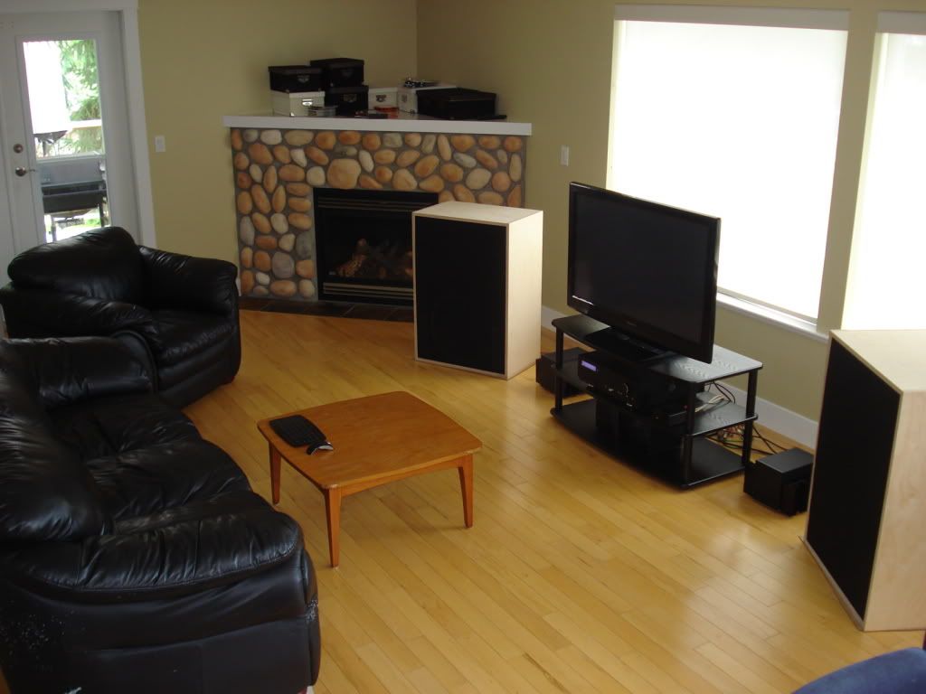
Here is a view of my sound system setup. My listening room is approximately 30’L x 16’W x 8’H with no room dampening, mostly hardwood floors and drywall. A very “live” room, with a fairly long RT60. I have the speakers set up on the long side of the room to minimize side wall reflections. I took this pic from the back wall overlooking the couch (i.e. listening position). The couch is about 4 feet from the back wall.

Here is a side view to show how far the speakers are away from the back wall and where the listening position is.
The measurement mic is placed on a mic stand behind the couch with the mic stand feet on foam so any transmission through the floor (the speakers are on Vibrapods – highly recommended) won’t be picked up by the mic. Use a tape measure so that the tip of the mic is at ear level and forms the equilateral triangle with the speakers.
One easy way to measure up is to cut 2 pieces of string that form the equilateral triangle and tape them in the exact same spot on the top of each speaker and hold them taught while moving the mic into position. Note that the mic should be exactly centered between the two speakers at the listening position.
A side note on measurement mics. Regardless of which measurement mic you opt for, ensure that a) it is calibrated and b) you have the calibration file. Have a look at my mic calibration file:

Side note. Notice the mic is calibrated for a “pass band” of 20Hz to 20kHz. Most acoustic measurements will be pass band limited to this range, not only by the microphone, but also by the swept sine wave the measurement software produces and subsequent results through the sound system back to the microphone. This is not an anechoic chamber measurement test to determine the frequency limits of the loudspeaker at 1 watt @ 1 meter. We are measuring the audio chain at the listening position in a real room in order to produce as natural timbre as possible in the pass band. That is our goal.
Side note 2. Timbre is (mostly) the tonal quality of the music reproduced. Ideally speaking, if I was to record the sound of an acoustic guitar in the room and then play it back over the sound system, I am expecting the tonal quality of the reproduced guitar to be as similar as possible to the live guitar. That's what I expect in the studio/control room, I also expect that in my home stereo as well.
Of course the source material and electronics chain plays a factor in timbre for sure. But it is the speaker to room interface that is the weakest link, by far. If you are using measurements as a way to gauge the difference, the speaker to room interface frequency response, at the listening position, has orders of magnitude deviation compared to an amplifier's frequency response for example.
Now that you have the mic setup, let’s turn to the software. Note that Audiolense also creates digital room correction files, but at this time, we are using the free portion of the software to take frequency response measurements at the listening position.

In this seetup screen for a stereo configuration, we are applying a swept sine wave from 20Hz to 24Khz over 10 seconds for each speaker. Be careful when doing this as you don’t want to blast the speakers into oblivion. You would like about a 90db or so measurement at the mic.
Now let’s run the frequency response measurement. Please refer to your sound card manual and Audiolense help file for the finer points of setup and operation. Here is the frequncy response measured at the listening position:

There are several things to infer here. One is the incredible detail of the frequency response measured. The first thing to do is look at a smoothed version (1/3 octave smoothing) that correlates more to what our ear can discriminate between frequencies:

Now how does this frequency response correlate to the B&K house curve mentioned in earlier posts? Side note, the purpose of this exercise is to implement the “target” B&K house curve as closely as possible as it is proven, from a speaker to room interface, to provide the most natural timbre. And as time will tell, it will also produce that elusive depth quality to the sound stage. Audiolense lets you “draw” your own frequency response targets, so I took the image from Figure 5 in http://www.bksv.com/doc/17-197.pdf and drew that exact target curve in Audiolense. Here is what it looks like relative to my measurement, it is the flat curve on top with the high frequency rolloff:

Listening to the sound system correlates to what is being measured on the screen. It is a bit bright sounding, which should come as no surprise as the room my speakers are in have little sound absorption. I seemed to have “voiced” (see Part 2 for voicing) the speakers reasonably well as there are no huge dips or peaks in the low end, save for that 200Hz peak. Also note the different amplitudes from each speaker at the listening position. What we really want is to have each speakers output identical over the frequency range. That will give us a dead center phantom image.
Note the overall shape of the filtered response to the B&K house curve target. Again a bit on the bright side and as a general rule, unless you have a really dampened room, most speakers, relative to the B&K house curve will be a bit bright. Unfortunately this messes with both the timbre and the perceived depth of the sound stage as we will see.
So now what? Ideally I would add dampening material to the room to bring down both the mid to high frequency response to be more in line with B&K house curve and to what my ears perceive. How much dampening? If you crack open any of the acoustic books from F. Alton Everst, it will tell you how to measure RT60 and calculate the number of sabines required to dampen the room at various frequencies. As someone that has been there and done that, it is a lot of work, but is quite rewarding once it is done and matches what you want.
However, with the advent of digital room correction software, in mere minutes, you can generate filters that are the inverse of the measured frequency response, apply it to the target, install the filters in a DSP like ConvolverVST, hosted in a media player like JRiver MC16 and voila:

And the listening result? Near perfect timbre and full depth sound stage.
We will look at this frequency correction result in detail in the next post, including a section on the next step, time domain correction.
Happy Listening!
Mitch


10 Comments
Recommended Comments